8

I'm thinking of using two regulators to create a ±5 V power supply. I'd use a 10 V regulator and a 5 V regulator and use the 5 V regulator's output as ground for the circuit and 10 V regulator's ground as the -5 V.

Something like this:

enter image description here

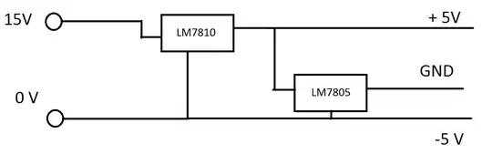
What's confusing me in this setup is how do I calculate the power of the + 5 V regulator.

I guess that the load of the 10 V regulator would be the load of the whole circuit (including the 5 V regulator). Would the load on the 5 V regulator then be only the return current going into the GND pin?

AndrejaKo
  • 23,261
  • 25
  • 110
  • 186

3 Answers3

11

Do not figure it out, junk it. Current cannot flow from the plus 5 to the ground because these 3 terminal regulators do not sink current. In rare cases it can work if the -5 draw is always greater or equal to the +5 draw. Look for voltage splitting circuits. A common approach is to use an amplifier to force the ground to ground, at low currents even an op amp can do this.

russ_hensel
  • 2,904
  • 16
  • 12
  • If the current drawn from the +5 will always exceed that drawn from the -5 supply, one might be able to rework the circuit using a 7905. There are some real scenarios where the -5 draw will never be very big, and the minimum draw from the +5 supply will exceed that. Even in such scenarios, it might not be a bad idea to add a 5.1-volt or 5.4-volt zener on the +5 supply to ensure that even if the expected load isn't present, the "5-volt" supply voltage will not get so high as to cause damage. – supercat Jan 30 '12 at 16:27
  • @supercat Can you write a bit more on that or post some links? Looks pretty interesting. – AndrejaKo Jan 30 '12 at 16:38
  • @AndrejaKo: Conceptually, it's pretty simple. If one were to eliminate the 7905 and simply let the "ground" be floating relative to the source supply rails, the ground would float to a point where the current sourced into "ground" from the "+5" rail was equal to the current sunk from the "-5" rail. It's not terribly likely, however, that that point would be halfway between the two rails. If one can be assured that the point would be above the midway point, one can use a chip like the 7905 to... – supercat Jan 30 '12 at 21:13
  • ...pull the ground down to a point that's "at least" 5 volts below the positive rail. Note that the 7905 would not prevent the "ground" from going more than 5 volts below the positive rail; if more current would be sinked into "-5" than sourced from "+5" when ground is midway between the rails, then "ground" would be pulled to a point more than five volts below the "+5" supply. – supercat Jan 30 '12 at 21:17
7

In theory, this should work. I'm not sure how it will behave in practice though. So, in theory you cannot drive a current higher than what the 7810 can supply.

Edit: See @russ_hensel's answer below. Will not work.

How much current are you driving?

Most virtual grounds need to be buffered. See some circuit examples at: http://tangentsoft.net/elec/vgrounds.html

If you are worried about cost and real estate, a simple resistor divider should work.

enter image description here

Which you can additionally buffer:

enter image description here

TLE2426 is an integrated way to go about doing that.

enter image description here

Edit: Explained myself a little better.

jeep9911
  • 1,163
  • 1
  • 9
  • 12
  • Is not worrying about part count the right discriminator for the second design? It's part count is smaller by two resistors. For the first design you list minimizing cost and real-estate as its advantages; if the TLE2426 is larger and more expensive shouldn't those be the "not worried about" items? – Dan Is Fiddling By Firelight Jan 30 '12 at 18:12
  • An op-amp/buffer virtual ground is the way to go. Since an op-amp can both source and sink current, it will not have the issues intrinsic to the regulator solution. – Connor Wolf Jan 31 '12 at 00:42
  • @DanNeely, you are correct. I wrote the answer too fast. Edited to reflect the changes. Thanks. – jeep9911 Jan 31 '12 at 22:12
3

I really like the way Dave Jones does it in the uCurrent design.

enter image description here

Conceptually, the point of the U2 op-amp is to set VGND to half the "battery" voltage. Then the battery voltage ends up being +V and the battery ground ends up being -V. You can substitute the battery voltage for any single ended supply (say the output of a 10V regulator) and that circuit will convert it to a double-ended supply. The op-amp will do the job of keeping your "virtual" ground at the center of your rails.

vicatcu
  • 22,499
  • 13
  • 79
  • 155
  • 1
    p.s. I noticed this is essentially what @jeep9911's first "buffered resistor divider" boils down to... still good to see a "practical" implementation that is in production – vicatcu Jan 30 '12 at 16:14