21

I sent my PCB a couple of days ago for fabrication but just realized a terrible error: I need to send 70mA to an IR LED with a 5V supply so I would need a resistor of about 70ohm, which means the resistor would be dissipating 350mW of power.

The SMD resistor package is 0805. THE PROBLEM is that I can only get one that dissipates max 125mW in this package : 70ohm 125mW from digikey

So can I get 3 220ohm versions of this resistor and literally stack them in parallel?
Has anyone tried this?

What can I do in this situation?

Shubham
  • 6,054
  • 12
  • 41
  • 55
  • 3
    This doesn't answer your question but it doesn't look like from your calculations that you are taking into account the voltage drop of the LED which I believe is about 1.9V for IR LEDs so you'd need 45 ohms or so to get 70mA. – John Burton Jan 29 '12 at 22:04
  • 1
    Although you would still need multiple resistors, by getting a slightly different value you can get a 1/4 watt resistor instead of a 1/8 watt one: [68.1ohm 250mW from digikey](http://search.digikey.com/us/en/products/RNCP0805FTD68R1/RNCP0805FTD68R1CT-ND/2240545). If you need a completely different value, as other have suggested, widen your search a little around the exact value you need to look for 1/4 watt parts. – tcrosley Jan 30 '12 at 00:04
  • Ah thanks, I ran another search and digikey also has 1/3 watt resistors in 68ohm. – Shubham Jan 30 '12 at 00:21
  • 1
    @Shubham: If the pads are big enough, could you squeeze in a slightly larger resistor? – Chris Laplante Jan 30 '12 at 00:49
  • The pads are pretty small, each pad is about 1.5mm x 1.5mm and they are spaced apart 0.5mm. I may be able to but the larger resistor still has to be able to dissipate almost 400mW. – Shubham Jan 30 '12 at 01:38
  • 3
    The important optimistic fact is that you miscalculated it, and since there is always some significant voltage drop on a LED, you won't need 400 mW resistor. If we count e.g. 1.3 Volt drop on LED, then resistor is 53R and power dissipated on it is only 250 mW. – Al Kepp Jan 30 '12 at 14:42
  • @AlKepp Ah ha, just did the Math and realized my mistake. Forgot to account for the voltage drop of the LED. Thank you this helps my situation! – Shubham Feb 07 '12 at 16:23

4 Answers4

13

I've seen stacked SMT resistors as a method for correcting resistor value. But I haven't yet seen it as a method for increasing power rating.

Two (2) stacked resistors could indeed dissipate more heat than just one (1). But the convective heat transfer from the bottom resistor will be hindered by the upper resistor, so the power rating of the stack would be less than 2x individual \$P_{stack of 2} < 2P_{individual}\$ .

Your desired power rating is 350mW. Nominally, you would need 3x 125mW resistors. You may have to use a larger number of resistors.

Is this a one-off or production? If it's production, consider changing the board.

Nick Alexeev
  • 37,739
  • 17
  • 97
  • 230
  • Its a one time production. It's a micromouse robot for a competition in a couple of months. Since boards take a couple of weeks to get back, this is the only one I have time to make. Thanks for the advice, I might try using 4 or 5 stacked resistors. – Shubham Jan 29 '12 at 22:54
  • 4
    Alternatively, could you "green wire" the resistor pads to a resistor mounted somewhere in/on your enclosure? That way, you could use a through-hole resistor which will have a higher power rating. – Chris Laplante Jan 30 '12 at 00:53
  • 1
    @Shubham, if you can a heatsink and thermal paste can do alot if you can find a way to mount it. – Kortuk Jan 30 '12 at 10:41
  • 2
    @Shubham, what simplecoder discussed is often called deadbugging if you want to google more about it(called that in memory of ICs that look like upside down dead bugs when this is done). – Kortuk Jan 30 '12 at 10:42
11

Two in series, stood vertically:

If you have vertical room you can place two resistors in series by standing them on the pads tombstone style and joining across the tops. It's likely that this will have similar wattage rating to two of the originals and possibly more as the resistors are further clear of the board surface. Working against this is that there is less cooling per resistor by conduction to the board copper, which is a significant cooling path.

If you stand the two resistors clear of each other with a wire bridge between them each could have substantially more access to cooling air than they have when lying flat.


Add a heatsink:

I've done similar to this on occasions with through hole components, with good results.

I've never seen it done with SMD resistors, but it would be easy to add an "ad hoc" heatsink by soldering copper wire of shim to the ends. I'd expect this to add significantly to the power ratings.


Use a 0.5 Watt SFR16 through hole resistor with formed leads.

The 0.5 Watt rated SFR16 through-hole metal film resistors have a 3.2 mm long x 1.9 mm wide body length and the wires can be formed back under the body so it produces contacts which fit 0805 pads correctly with the resistor aligned in any of a number of ways to suit the mechanical situation.

eg the resistor can be stood vertically so it has about 3.5mm height or fitted over the pad horizontally or out to one side.

SFR16 ~= "1308" compared to the original 0805 but the leads allow forming to fit any of a wide range of pad sizes and body irientations.

An 0805 = 0.080 " x 0.050" =~ 2mm x 1.25mm

An SFR16 ~= 0.14 x 0.08 = 3.4 x 1.9 mm

enter image description here

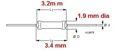
The (originally Philips made) SFR16 resistor is about the same physical size as a 1/8th Watt typical through hole part but which is rated at 0.5 Watt dissipation. SFR16 datasheet here - 3.2 mm body length

The diagram below demonstrates that for the SFR16, radiation and convection from the body and leads forms a significant part of the heat dissipation system. The PCB mounting point temperature decreases with increasing lead length

enter image description here

Russell McMahon
  • 147,325
  • 18
  • 210
  • 386
  • 1
    Really great formatting and very interesting idea, vertically putting them in series, I have seen vertical through hole to increase power dissipation, but this is pretty smart. – Kortuk Jan 30 '12 at 15:43
  • Yes, great idea. I will look into trying this out. Thank you! – Shubham Jan 31 '12 at 05:41
7

The amount of stationary power a resistor can dissipate is determined by its maximum temperature and the amount of heat it can get rid of. Stacking two resistors on top of each other hardly increases the total area, so it won't help much. If you can place the two next to each other (so both are flat against the PCB) they can each dissipate (almost) their full rated power.

But do you really need the 70 mA, and do you need it 100% of the time? If this is for IR communication, the duty cycle for 'signal on' is likely to be 50% or even lower, and the signal-on to signal-off ratio is likely well below 50% too. If this is the case, check the maximum peak power and you might be in the clear.

If you end up using less than 70 mA: assuming the IR output is linear with the current (check your datasheet, it might be not), the distance at which you get the same amount of IR light on a surface is linear with the square root of the current, so reducing your 70 mA to let's say 20 mA reduces you reach by only sqrt( 20/70 ) = 0.53

But: 0.07 A * 5 V = 0.350 W, which that assumes no power is dissipated in the IR LED. Check your datasheet, but let's I assume the IR LED drops ~ 2V, that leaves 0.07 A x 3 V = 0.210 W for the resistor. (And there is probably some drop in the switching element, a FET? bipolar transistor? don't try to let your microcontroller sink 70mA!)

Also: 5 / 70 = 0.070, but that again assumes all voltage is dropped by the resistor. Back to the drawing table, Shubham!

Wouter van Ooijen
  • 48,407
  • 1
  • 63
  • 136
  • This is for distance measuring for a micromouse robot, and because of the design, unfortunately they need to be running at 70mA at all times. Thanks for the insight, I will see if there is enough room on the board to put two side by side, then perhaps stack 2 more on top of them. – Shubham Jan 29 '12 at 22:58
  • 2
    For continuous use you still hve to re-calculate the R value and the dissipated power using the voltage drop in the LED! – Wouter van Ooijen Jan 30 '12 at 06:28
3

This may work. The dissipated heat is drained to the environment via convection through the air surrounding the resistor and via conduction through the solder connection to the PCB's copper. Stacking resistors will compromise the convection, but we don't have to worry about this too much since there's a lot more heat drain through the conduction path. So make sure you apply enough solder to the terminals and you'll be fine.
Of course this solution is a manual fix only and can't be used in production.

stevenvh
  • 145,145
  • 21
  • 455
  • 667