2

I've been drawing the circuit diagram for a crystal radio I am going to build. (This is my first real electronic project). By using the theoretical knowledge I have, I figure I should have to have an LC series circuit (for the discrimination of the waves) like so: (please note that the numbers attributed to the figures do not mean anything, this is purely qualitative)

schematic

simulate this circuit – Schematic created using CircuitLab

However, upon researching other designs, I see the LC element of the circuit in parallel like so:

schematic

simulate this circuit

I don't understand how the parallel one would work, by what I understand, if the reactance of the inductor=the reactance of the capacitor in parallel, there should be no current passing at all whereas this is the perfect setup in my series diagram where in this case (capacitor reactance = inductor reactance), the receiver should favor a specific frequency.

Could anyone clear me up on where I'm going wrong and whether my design (first diagram) would work? Thanks for any responses

SamGibson
  • 17,231
  • 5
  • 37
  • 58
Anthony B
  • 127
  • 1
  • 4
  • i ***still*** cannot understand what a 1N4148 diode is doing in a passive crystal radio. you need a ***much*** lower turn on voltage. it should be a Ge diode ***not*** an Si diode. – robert bristow-johnson Sep 19 '16 at 23:26

4 Answers4

5

Yes, you are going wrong with your thinking. A parallel tuned circuit when fed from an antenna that is predominantly "short" will convert a very low amplitude signal to a relatively high amplitude voltage.

I mention that the antenna is "short" and by this I mean it is significantly less than one-quarter wavelength at the desired tuning frequency. This makes the antenna's impedance as seen by the parallel tuned circuit capacitive. So now, a signal snatched from the ether by the antenna feeds a parallel tuned circuit via a capacitor (the antenna itself) and the important thing here is that there will be significant voltage amplification.

That voltage amplification is basically the Q of the tuned circuit and this voltage is large enough to be properly rectified by the diode. This rectification returns the envelope of the carrier as a base band signal and this can be heard through high impedance headphones (not an 8 ohm speaker).

A series tuned circuit won't work at all because there will be no voltage amplification and the signal appearing at the input to the diode although somewhat correctly tuned, will be miniscule in comparison. I say somewhat correctly tuned because, in fact, the Q of this circuit is very low due to the high signal impedance from the antenna. In other words, this high impedance is useless for series tuning and perfect for a parallel tuned circuit.

Andy aka
  • 434,556
  • 28
  • 351
  • 777
  • my question is why would anyone use a 1N4148 or any of these Si diodes for a crystal radio?? that makes no sense at all. they need like 0.7 volts or more to kick on. i can't imagine that much coming out of a totally passive receiver with no amplification. – robert bristow-johnson Sep 19 '16 at 22:49
  • back in the olden daze, we used the [Ge diode, 1N34A, for the rectifier in a crystal radio.](http://www.techlib.com/electronics/crystal.html) – robert bristow-johnson Sep 19 '16 at 22:50
  • Wouldn’t it also be because parallel tuned circuit typically work with current sources and antenna can be like current source due to magnetic field fluctuations being induced across it? This in contrasts to a series tuned which works better with a voltage source? – Leoman12 Apr 22 '20 at 16:28
  • @Leoman12 I'm not sure what this means: *"due to magnetic field fluctuations being induced across it?"*.... or maybe you are addressing someone else not me? Also, have you checked what the dominant impedance component is of a short antenna? – Andy aka Apr 22 '20 at 16:32
  • Yeah I meant to ask you @andy aka. What I meant is the induced current in the antenna from incoming Electromagnetic waves. Any electrically short antenna would be capacitive and any electrically long antenna would be more inductive. Only at resonant frequency would it be resistive. – Leoman12 Apr 22 '20 at 16:50
  • @Leoman12 I'm unsure what you are asking me. – Andy aka Apr 22 '20 at 16:53
  • Reason I mention the antenna acting like ac current source is because then it would make more sense to use parallel LC since it produces max Vout when resonant due to most current flowing across output resistance. If it was a voltage source across parallel LC, the voltage output would always remain the same since everything is in parallel. Basically I’m asking if this would also be why parallel LC is used instead of series LC in addition to your answer. – Leoman12 Apr 22 '20 at 16:54
  • If you regard it as a (very) remote voltage source feeding through a capacitor to a parallel tuned circuit, you get the answer. There are of course better ways to improve the voltage received by using a tapping lower down on the inductor (or something like [this](https://www.electronics-notes.com/images/crystal-radio-circuit-with-input-matching-01.svg)) but that is beyond the scope of this question. – Andy aka Apr 22 '20 at 17:01
0

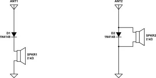
A simplification of your two circuits may illustrate why your first cannot work, while your second can work. The simplification involves eliminating L's and C's leaving antenna, diode and audio transducer:

schematic

simulate this circuit – Schematic created using CircuitLab I have replaced your 8 ohm speaker with a 2K ohm audio transducer, like high-impedance headphones. This substitution results in far more audio. In both cases, motion of the speaker or headphone's cone results from current flowing through a coil in the presence of a permanent magnet.
The leftmost simple circuit is equivalent to your first series circuit. It produces no audio for SPKR1 because there is a very weak return path for audio currents back to the antenna - through the antenna's capacitance-to-ground. Any audio signal produced will appear between the diode's anode and ground - the antenna gets the audio, not SPKR1.
The rightmost simple circuit is equivalent to your second "parallel" circuit. Here, the antenna signal appears across both the diode and SPKR2. Positive peaks of the radio signal cause the diode to conduct. The diode shunts these antenna currents directly to ground, so that speaker current is small. Negative peaks of the radio signal are not shunted to ground by the diode, but pass through SPKR2. These pulses of current produce audio in SPKR2.
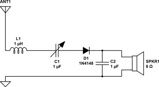
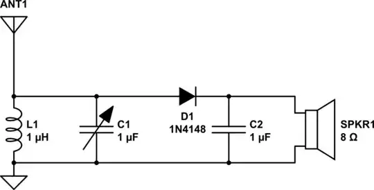
In your second circuit, the audio current loop passes through L1 (1uH), SPKR1 (8 ohm) and D1 (1N4148). The reactance of L1 is miniscule for audio, compared to the reactance of the 8-ohm speaker, so audio is delivered to SPKR1.
In your first circuit, the audio current loop includes ground, SPKR1, diode, C1 (a 1uf variable!), L1 (1 uH), Antenna, and a tiny capacitor between antenna and ground. Any current in this loop is pretty much killed by the extremely high impedance of this tiny capacitor.
I have built both versions of my "simplified" crystal radio, and can verify that the leftmost produces no audio, compared to the rightmost, which produced painful audio from the nearest AM source.


One must be very careful about using linear circuit analysis in this case, because the diode is an important non-linear element. The diode becomes a signal source for audio rather than the antenna, complicating analysis considerably. In this case, a SPICE TRANSIENT ANALYSIS gives a more complete picture, so long as equivalent circuit is properly presented. A SPICE analysis of these simplified series & parallel circuits follows.
First - what is the equivalent circuit of the antenna? For AM broadcast band, let us assume a thin wire Marconi-type antenna, extending vertically for 30 feet above a perfect ground. Choose a simple mid-point on the broadcast band - 1 MHz. At 1 MHz., this is a short non-resonant antenna whose equivalent circuit is a resistor and capacitor. ARRL ANTENNA BOOK gives formula for short wire antennas:
$$ R_{s}=273 \times 10^{-8} ({lf}) ^2 $$ where l=inches wire length, f=frequency (Mhz)
$$ C_{s}={{17 L} \over {[ln{24 L \over D}-1]} \times {[1- {fL \over 234}^2]}} $$ where L=wire length above ground (ft), D=wire diameter, inches.
For this example, I calculate antenna equivalent Rs=0.354 ohms, Cs=59pf
Into ORCAD SPICE, a crude signal voltage source simulates an AM-modulated carrier wave of 1 MHz. It's modulation isn't sinusoidal, but adequately illustrates the different behaviour of the series circuit (on the right side this time, and the parallel circuit (on the left side this time). Amplitude is very large, (10v peak for each source). A proper model for the speaker is quite complex, and has been reduced to a 1K resistor: SPICE parallel diode (left), series diode (right) with Rs,Cs for antenna

A transient analysis is run with max time-step of 10ns., so that all the 1MHz pulses are properly stepped through. Since speaker current is the motive source for moving its cone, current through the 1K resistor is shown: Transient plot of current through series SPKR1 (red), parallel SPKR2 (grn)

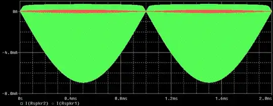
The parallel diode-SPKR2 yields the expected large current, which will be audible. The series diode-SPKR1 yields very small current, which is very much attenuated - the missing audio appears across the 59 pf capacitor of the antenna equivalent (Cs).

glen_geek
  • 23,591
  • 1
  • 22
  • 50
  • 1
    Not only have you drawn the equivalent circuits incorrectly, your analysis ignores the voltage multiplication effects of the tuned circuit and, it is this effect that delivers enough signal to overcome the forward diode drop voltage. – Andy aka Sep 18 '16 at 09:24
  • @Andyaka -If my argument has failed to convince you (an astute practitioner), then it is poorly presented. Another try...The series circuit fails because **audio** must find a path from antenna back to ground. I am assuming a long-wire antenna. A loop antenna in the series circuit hasn't this failure mode, because it presents a low-impedance path for audio - ground is not required in this case. – glen_geek Sep 18 '16 at 12:55
  • XTAL radios are used at about 1 MHz where the wavelength is about 300 m. A quarter wave (long) antenna will be 75 m. Do you really think that people will bother to use anything of the length of a qtr wave monopole when building this type of radio? – Andy aka Sep 18 '16 at 13:28
0

The Electrically Short Antenna that the practical crystal set uses looks like a small resister in series with a small capacitor .This at MW means high impedance .The unpowered and therefor unbiased diode detector does have significant drops meaning that it is much more efficient at relatively high voltages and low currents.This means that the diode detector is a high impedance device .The parallel tuned circuit has high Q at high impedance which is essential when there is only one tuned circuit for selectivity .The series tuned circuit has high Q at low impedance so it will not work well if at all even if a DC path was provided for the diode.A series tuned circuit can enhance a crystal set if it is placed in series with the antenna .What I tried was resonating the antennas capacitance with a slug tuning inducter from a dead AM car radio .This worked very well .This is really just a loading coil .The tuning was rather sharp .

Autistic
  • 14,235
  • 2
  • 27
  • 65
0

First circuit may work only if located a few meters from the transmitter even then it still would be a bad choice. Crystal radios are less capricious to adjusting the resonance when the signal level is very high compared to the usual level far from the transmitter where you have to extract the weakest signal.

Todor
  • 1