Recently I repaired one broken electronic ballast of a linear 30W fluorescent lamp. Now it seems to be working as expected, but I had to make some changes to it and I'd like to ask if you see any hidden problems I can get into due to those changes.
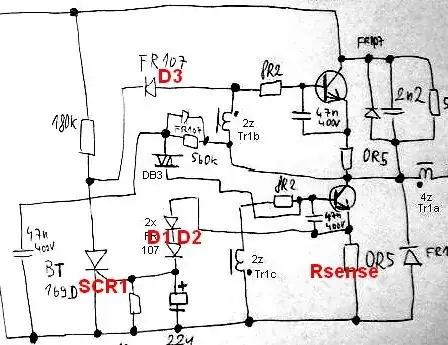
Here is the diagram. It is not exactly my diagram, but very similar and I hope fully usable here: 
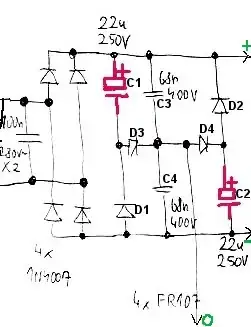
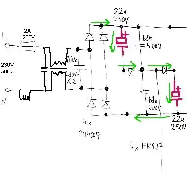
On left side you can see power source (230VAC, 1:1 transformer, diode rectifier). Look at those two (red) electrolytic capacitors in series. I assume they are charged to 162 volt only (Vpeak is 325V, so each cap gets 162 V only). The original caps were rated 15uF 250V, and I needed to replace one of them. I wasn't able to obtain the same for a good price, so I replaced only one of them with a 22 uF 250V. So now I have one old 15uF, and one new 22uF. (I cannot put there two 22uF, because they're too big. One old small 15uF and one new bigger 22uF can fit there.) My question is simple: What did I cause by this? Will there be problems?
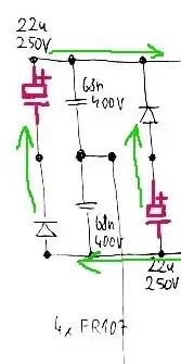
Those caps are surrounded by a lot of diodes. I expect that normally the potentials around and between those caps are -162V, 0V, +162V. When I replaced one of them by a different one, I probably moved the center potential out of ideal zero. Does it matter here? (The capacitors are never 100% ideal, so I hope the ideal zero potential isn't required here.) I am affraid I don't understand how this strange rectifier actually work. According to the diagram, It seems to me that now one of the transistors work with the higher voltage, and the other one with a bit lower voltage. Or am I wrong? Maybe those two capacitors are discharged in parallel thanks to those diodes so it doesn't matter whether they ar absolutely the same or not. (Vpeak on both transistors is 325V, but when mains voltage goes down the transistors are powered from capacitors, and each of those capacitors have probably got a different charging voltage. This is all too compliceted to me...)
Note that the reason why there are two strange capacitors instead of one 400V one is probably just the space. Two smaller 250V caps can fit into restricted space, one big 400V cap woudn't fit there. Here is the real photo:
My second question: I also had to make one more change: The 0R5 resistors on emitters of each transistor are now 0R56. I am affraid I don't understand what I caused by this, if it's dangerous change or not. (Again, I wasn't able to obtain the pretty same resistors as were the originals.)
The fact is that the ballast seems to work perfectly now, and the tube nicely shines. :-)
Epilog: I still hope that thanks to those diodes, the two electrolytic caps are always discharged together in parallel, so it actually doesn't matter whether they are the same type or not.