I am just getting into coils - I need 110VDC for some loud ringing apparatus. You'll have to forgive my inexperience. I'm very curious about best practices for making a long-lived transformer (possibly heatsinked if that's an issue). So two coils are needed, and what else? Google abounds with info, but I want to get the right parts and formulas and components off the bat, and also not die. The apparatus I need to drive is of the old PSTN type, which got its jolts from the landline. Thanks in advance, cluebats at the ready.
Asked
Active
Viewed 477 times
0
-
You are trying to ring a phone? or what? – Tony Stewart EE75 Sep 07 '16 at 18:44
-
No, it's a loud ringer for POTS, was used to notify people about a call. I want to repurpose it for a arduino clockradio (sans the radio). – user400344 Sep 07 '16 at 18:46
-
POTS is 48Vdc. what model? got a link? – Tony Stewart EE75 Sep 07 '16 at 18:49
-
2POTS ring voltage is about 90V 20 Hz AC, if I recall correctly (in North America). Do you have an old ringer, or are you trying to build one? – Peter Bennett Sep 07 '16 at 18:54
-
It's a scandinavian ringer - could be AC. It's not marked as anything but '110V'. It is noname.I wouldn't like a 110VAC ringer on my alarm clock though. – user400344 Sep 07 '16 at 18:59
-
It's got a striker arm which alternates between banging two bells. – user400344 Sep 07 '16 at 19:00
-
1@user400344: You are causing some confusion with your folksy style post which isn't really appropriate for a technical Q&A site. Also on this site we thank afterwards by up-voting and accepting answers. A photo would have been nice and explanation of the acronyms for those not familiar with them. See [Help center](http://electronics.stackexchange.com/help). Welcome to EE.SE. – Transistor Sep 07 '16 at 19:02
-
I concur, PSTN (public switched telephone network) ringers were generally low freq AC at shocking (literally) voltages that are a hang over from the hand cranked alternators. The ring signal was 90V AC coupled so it would be able to work even when the line voltage (typically 48V DC) was DC isolated when all extensions were on-hook. Voltages and frequencies varied a bit by country. – KalleMP Sep 07 '16 at 21:20
-
Another note: The minimum on-hook load was \$5M\Omega\$ -- you couldn't draw much current from it. – jonk Sep 07 '16 at 21:26
-
"It's not marked as anything but '110V'." - that sounds like a power input, not ringing voltage. Can you show us a picture of the inside of the unit? – Bruce Abbott Sep 08 '16 at 05:33
3 Answers
1
Another possibility is below with a small 10:1 transformer used as a stepup transformer. Choose cap RC time constant near 20ms for each half cycle or 25Hz, which is common for Europe. Then tune to get resonant frequency of spring toggle bell for max volume. This is fairly low current and turns ratio can be adapted to other supply voltages. EST. 1W max.

Tony Stewart EE75
- 1
- 3
- 54
- 182
-
Cool design - what reference formulas do you use to calculate coil turns and diameter? Note: we use 230V @ 50Hz here – user400344 Sep 08 '16 at 08:10
-
@user400344: Found this link yesterday, which the above schematic reminded me about: http://www.next.gr/telephone/ringers/20Hz-signal-generator-phone-ringing-circuit-diagram-l57893.html – jonk Sep 08 '16 at 19:07
-
@user400344 This does not operate off the power grid 50/60 but inverts Dc to a 25Hz bell ring tone for old solenoid bells. so look for a .240>24 XFMR and use in reverse @ jonk Imagine that inverter would work as well if you can find the transformer, – Tony Stewart EE75 Sep 09 '16 at 03:54
-
12V input - What about the properties of the transistors and other components? I never generated AC before. Got a bunch of TIP120s laying around... My resistors are all for 0.25W. Got insulated copper wire of the type used for coils as well - how many meters do I need? And coil turns + diameter? – user400344 Sep 09 '16 at 07:29
-
-
yes 10W will ring an old phone or two easily start with phone impedance work back to >20* Rce , where Rce= Vce(sat)/Ipk to compute using hFE=20, then R values then C for 25Hz or use555 timer – Tony Stewart EE75 Sep 09 '16 at 12:27
-
use555 timer , invert and drive 2 transistors may lead to smaller C values or FET & cap as @jonk showed with same 1:10 boost 10VA transformer – Tony Stewart EE75 Sep 09 '16 at 12:33
0
If the ringer is complete you should find a series capacitor in it to block DC. The ring signal is AC.
I agree with @PeterBennett. As far as I remember the ring signal was generated by a low-frequency alternator in the telephone exchange. It should, however, still work at 50 or 60 Hz. I suggest you try to find a transformer to suit your mains with a secondary of 30 to 100 V to test it out.
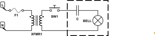
simulate this circuit – Schematic created using CircuitLab
Transistor
- 168,990
- 12
- 186
- 385
-
@user400344: I recommend that you unaccept for a day or so to encourage some other answers. You may get a telephone tech who is more familiar with the circuit. Thanks. – Transistor Sep 07 '16 at 19:14
-
I am terribly disappointed that it's AC. I can't use it for my alarm clock then. Thanks for the info – user400344 Sep 07 '16 at 19:14
-
-
@user400344: See added answer quoting from a manual I do have. Sadly, I can't say how well it covers your phone. But it may help out. – jonk Sep 07 '16 at 21:21
-
The capacitor would have been part of the phone circuitry if the bell was a fixed option, however it should have been included if it was a external accessory ringer. You could possibly make a DIY square wave inverter with an H-bridge hooked up to a suitable transformer wired backwards for step up operation. – KalleMP Sep 07 '16 at 21:25
0
I have a copy of the ANSI T1.401.1993 handed to me personally by an active standards committee member back in 2004. I recall that the standard attempted to "cover all bases" with commonly found systems in the US, which themselves varied a lot. (It lists many dozens of systems that are specifically covered in the standard.)
Section 5.4.2.1.1 Ringing Signals: In most cases, the network shall provide an ac ringing signal between tip and ring at a frequency of 15.3 to 68 Hz with a voltage at the NI of 40 to 150 V rms. (A note says here that it may be as high as 175V rms in some cases.) The crest factor of the ringing signal will normally be between 1.2 and 1.6 and almost always between 1 and 2. The DC component, when supplied, shall be in the range from 0 to 105V (positive or negative.) On some lines with analog carrier systems, the ringing signal consists of 200V dc pulses applied between ring and tip, at a 20 Hz rate, and with a duty cycle of 50 percent. During the "off" period in these cases, a low resistance is provided between ring and tip to allow ringing capacitors to discharge. Note: The most common ringing voltage frequency is 20\$\pm\$3 Hz with an ac magnitude at the NI of 40 to 106V rms superimposed on a dc voltage of less than 80 volts dc. Newer network equipment produces a ringing signal with a frequency of 20\$\pm\$1 Hz.
The fact that there can be a significant DC component is interesting.
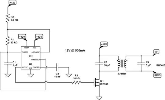
EDIT: I found this youtube link which describes the following circuit:
simulate this circuit – Schematic created using CircuitLab
No indication about the exact transformer details, but it's not hard to infer them. It's not from AC here. I know that. Just thought I'd add this as a lark. There is also this EE.SE link to look at, as well. Finally, there is this HV430 datasheet to look at. Probably mostly unobtainium except for the fact that Microchip bought them up (and they support ICs pretty much forever, from personal experience.) You can buy one here.
-
See also http://www.sandman.com/ringvoltbul.html - http://www.jkaudio.com/article_10.htm - http://ftp.tiaonline.org/TR-30/TR-30.3/Public/xDSL%20Documents/39904620.doc – KalleMP Sep 07 '16 at 21:27
-
1@KalleMP: Interesting page. Will mark it. I already have the full formal standard for my area, also. But interpretation helps. My interest had been in creating line-powered circuits to allow me to see if the line was in use, with an LED I could see. The \$5M\Omega\$ limitation was a tough one for me. But I managed to beat it! – jonk Sep 07 '16 at 21:30
-
I made a number of small mods and helpers to POTS connections in the past. Used to muck about with least-line and POTS modems a lot too. I recently purchased two vintage all electric dial phones to demonstrate them to my kids who have never had to use a dial phone. I plan to build a simple 2 or 3 point intercom perhaps with perhaps just 3 x PP3 batteries and a cap and resistors or perhaps something more to decode dial pulses and generate a ring, just for fun. – KalleMP Sep 07 '16 at 21:38
-
1@KalleMP: That's a cool idea. (I've seen examples where others have done that, as well. But never felt a mood strong enough to go for it here.) I keep old phones at home because we lose power and I have a medically fragile child living here. Having a ground line means we can make a critical phone call, if needed. (A service that is rapidly diminishing in availability in the US and will eventually completely disappear, I fear.) – jonk Sep 07 '16 at 21:50