-1

I understand that similar questions have already been asked but haven't been able to apply them on my problem.

I am working on Double integrator circuit as below (to simulate a physical system for my project on control system performance): enter image description here
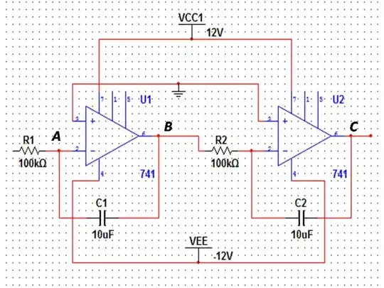
The actual input to point A is expected to take values from -2.5V to +2.5V. The circuit (physical one) is not working as expected, which has me guessing on the location of possible fault in it. Replacing both OPAMPs (UA741CP) and checking the capacitors(C1 and C2) didn't help much and now my doubt lies on the polarity of these capacitors (which sadly I didn't notice while taking over the circuit). As my input range is both negative as well as positive i am not sure about them. Could some one help please.

Secondly, given the circuit, if I want to check the individual integrators, by applying signal to A (DC pulse train maybe?) and monitoring output at B for IC1 (one on the left) and similarly at respective points for IC2 (pardon for not having marked). Should it work, or having been connected the circuit behaves differently as opposed to two integrators in isolation. Pardon my parlance for I have not much of electronics background. Thanks

EDIT

Output observation. As my knowledge of control system theory is limited, I'll do my best to explain my setup concisely (as I have understood). The actual system is created in levels cascaded as below:

1) Arduino as controller (8bit output) --->

2) DAC using DAC0808 and UA741 --->

3) -2.5 voltage shifter ---->

4) Integrator circuit (simulating the Plant and the one questioned) --->

5) Analog inputs to arduino as Plant state output which are worked upon by the arduino and the actuation value is calculated and sent back to it via route 1) through 4)

Upon setting state space parameters in the controller code. The Plant (output voltage) could be brought a desired reference point (in a given range 2~5V, as I have dont it previously on the same circuit). Now it does not. The output voltage would stay very low 0~500mV irrespective of control input.

I could test the other circuits (DAC and level shifter) by applying inputs and monitoring them. Couldn't find anything definitive with the integrator though.
  • Have you simulated the circuit? (there are numerous tools available, some free). There are many non-polarised capacitors available, and single polarised devices are not suitable for this circuit. – Peter Smith Sep 07 '16 at 11:03
  • @PeterSmith : Although I haven't, but this circuit has been working previously. Hence my suspicion on a 'fault'. – sherinkapotein Sep 07 '16 at 11:22
  • 4
    What kind of voltage is '500mA'? – Spehro Pefhany Sep 07 '16 at 11:34
  • What load impedance is this thing driving? –  Sep 07 '16 at 11:53
  • 1
    LM741 is a VERY old amp and MUCH better are available - possibly at lower cost. | Series opposed electrolytics as a non polar capacitor is doable BUT not good for instrumentation circuits where accuracy and stability are wanted. | Leakage is poor and variable, capacitance is pow accuracy (usually) and ... – Russell McMahon Sep 07 '16 at 12:41
  • @BrianDrummond : The output of first integrator (point B) is being fed to a voltage level shifter circuit (as input to another 741 through a 10K resistor. The output of second integrator (point C) is being fed to Analog input pin of Arduino Uno. – sherinkapotein Sep 08 '16 at 03:47

1 Answers1

4

Note: I assume below that your expectation of voltages at point A being +/-2.5V actually refers to the left side of the 100K resistor. Point A should not be more than a few mV either side of ground until the integrator output rails, at which point it should gradually (exponentially) approach the input voltage with time constant 1 second.


The circuit you have shown is correct and should work properly. You should use non-polarized film capacitors for this application. Mylar is acceptable if really high accuracy is not a high priority-- they have significant dielectric absorption (DA) which will cause errors in the sub-1% region.

enter image description here

If you are using polarized electrolytics they will not operate properly when the voltage reverses. You can get bipolar electrolytic low-leakage capacitors which will work okay, but it's better (and probably easier for small quantity) to just get film caps. You could also do a quick test with two polarized 10uF caps back-to-back but it's not going to work very well (Edit: the effective capacitance will be 5uF so you can either use 200K resistors or use 20uF caps).

Ceramic capacitors are another possibility, but the accuracy will likely be terrible because they have a large (negative) voltage coefficient, so your integrator will curve faster as the output deviates from 0V (for a fixed input voltage) rather than following a straight line.

To test the circuit, observe the output voltage of each integrator with a fixed input voltage of (say) 0.1V applied, then reverse the input voltage. The output should ramp at 0.1V/second until it rails at about +/-10V, so it will take about 20 seconds to ramp from one rail to the other.

If the output is at (say) +10.5V, then applying +0.1V should cause it to ramp downwards until it gets to about -10V. It's easier to break the connection between the two integrators at point B and test each one separately. Any deviation from linearity will likely be a result of capacitor imperfections (leakage or DA).

Spehro Pefhany
  • 376,485
  • 21
  • 320
  • 842
  • Those WIMA caps look good and expensive.A better opamp would support say 1 meg resistors and say 1 microfarad caps. This may be overall cheaper. – Autistic Sep 07 '16 at 11:16
  • 1
    "two polarized 10uF caps back-to-back" ... shouldn't that be 20uF? From [CDE's Application Guide p13](http://www.cde.com/resources/catalogs/AEappGUIDE.pdf), Aluminum Electrolytic Capacitors: "If two, same-value, aluminum electrolytic capacitors are connected in series, back-to-back with the positive terminals or the negative terminals connected, the resulting single capacitor is a non-polar capacitor with half the capacitance." – Tut Sep 07 '16 at 11:23
  • or did you mean in parallel with opposite polarity? – sherinkapotein Sep 07 '16 at 11:26
  • Series with opposite polarity (connect both + or both - terminals). As Tut says the effective capacitance will be halved. – Spehro Pefhany Sep 07 '16 at 11:32
  • @sherinkapotein From page 13 of Tut's reference - which you should have read before asking the same question. "If two, same-value, aluminum electrolytic capacitors are connected in series with the positive terminals or the negative terminals connected together, the resulting single capacitor is a non-polar capacitor equal in capacitance to half of the rated capacitance of either of the original pair. The two capacitors rectify the applied voltage and act as if they had been partially bypassed by diodes. ... – Russell McMahon Sep 07 '16 at 12:37
  • ... @sherinkapotein: ... However, at all levels of AC voltage the apparent capacitance is half of the rated capacitance as you would expect for capacitors connected in series. The nonlinear performance produces distortion where non-polar aluminum electrolytic capacitors are used in audio AC applications. " – Russell McMahon Sep 07 '16 at 12:37
  • I'm not 100% sure they behave exactly as 1/2 capacitance during startup transients of more than a few hundred mV. I think @RussellMcMahon has a long answer on SE that addresses [Edit: Here](http://electronics.stackexchange.com/questions/21928/can-you-make-a-non-polar-electrolytic-capacitor-out-of-two-regular-electrolytic) exactly what happens. After the midpoint of the capacitors charges they do behave as advertised, but that's not much comfort if you care about what happens up to that point. – Spehro Pefhany Sep 07 '16 at 12:43
  • @SpehroPefhany What would I know :-) ? | I'd not use them in this application (and I imagine you wouldn't either) but it seemed worth pointing out that the answer was in the reference already provided. Not wishing to be 'mean' but the 'good cop' has to keep the clients in line so the 'bad cops' don't get them :-). FWIW - all we 'cops' have the same aid - help beginners climb the ladder to quality questions and technical capability. It's just that some differ from others on best-methods :-). – Russell McMahon Sep 07 '16 at 12:49
  • @RussellMcMahon ... You may want to repair the link to the CDE app guide in your answer that Spehro mentioned: http://electronics.stackexchange.com/a/21932/25328 ... I would have repaired it myself, but you mention page numbers that don't seem to match the guide in my link. – Tut Sep 07 '16 at 13:18
  • @Tut Thanks. I wondered if it was old age - but no - [This link](https://www.yumpu.com/en/document/view/13737977/application-guide-aluminum-electrolytic-capacitors) shows a version with the page numbers I used. - but not a good source. Bed calls. I'll look at the best way to tidy that up 'soon'. – Russell McMahon Sep 07 '16 at 14:11