0

I'm testing my first ever OP amp circuit and I ran into a problem.

I have done the following circuit (see picture). The 0 - 3.3V called uC is coming from a Nordic nRF24LE1 PWM and RC filtered output. I'm using a LM741CN op amp and try to follow the circuit on allaboutcircuits (http://www.allaboutcircuits.com/textbook/semiconductors/chpt-8/voltage-to-current-signal-conversion/).

I assumed that if the uC outputted 3.3V i would get around 20mA through the 85Ohm resistor and if it output 0V I would get 0mA and everything between for the other values.

But for some reason it will never go over 3.37mA. When I output around 520mV the difference between OP amp inputs are almost zero. But when I step up to the next level, 573mV I start to get some voltage between the Op amp inputs (47mV for that level) and it increases the more I raise the input voltage. Why is this happening. Is the op amp not suitable for this type of operations. If so what OP amp should I look for and what is the key specifications?

schematics

Best regards RS

Math Keeps Me Busy
  • 18,947
  • 3
  • 19
  • 65
RedSmolf
  • 171
  • 8
  • Please share a schematic of the circuit you actually built, including all power supply connections, bypass capacitors, etc. Without it we can only guess where you went wrong. – The Photon Sep 03 '16 at 18:23

1 Answers1

1

The problem is the way you power the op-amp. Your bias scheme does ensure that there is 36 V between the V+ and V- rails of the amplifier, but it doesn't ensure that V- is at -18 V and V+ is at +18 V.

For example, look what happens if you set your input voltage (uC) to 0.56 V. Now the op-amp will, if it's operating in its linear range, take 3.4 mA from the positive supply and drive it out of its output pin, which flows through R4 and R3, producing 0.65 V on the IN- pin, completing the feedback loop.

But after flowing through R3, where does that 3.4 mA go? It needs to return to the negative terminal of the power supply. So it flows through the ground connection to R1, and through R1 to the supply's negative terminal.

But 3.4 mA times 10 kohms is 34 V, so this means that the negative terminal of the supply is at -34 V. Therefore the positive terminal of the battery is at +2 V. But the LM741 can't drive its output pin higher than 2 V below its positive power terminal (for load of 2 kohms, according to the TI datasheet. For the 250 ohm load in your circuit, the limit will be even lower). So this is going to drive the op-amp into saturation. You're not going to get a higher output voltage from the op-amp, or more current through the load (R4).

What can you do to fix this?

Your options include

  1. Use a less stiff divider to set your ground reference relative to the supply terminals. But this will start to waste substantial power if you make it compliant enough to deal with 20 mA return currents.

  2. Use proper independent +/- 18 V supplies, each with its own ground reference.

  3. Use another op-amp or linear regulator circuit to hold the virtual ground node at 18 V below the positive supply terminal.

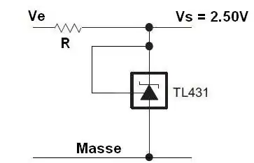
  4. Use a shunt device to set the virtual ground voltage. For example a 15 V zener diode in place of R1 could easily be chosen to allow an additional 20 mA to flow without the power supply node voltages changing by more than a few 10's of mV relative to the ground node. Note that with 20 mA output current, the op-amp will be consuming around 320 mW and the zener will be consuming about 330 mW, so you will need to choose your packages accordingly.
The Photon
  • 126,425
  • 3
  • 159
  • 304
  • I actually have two Agilent lab supplies. Both able of producing at 18V. Can I connect them in series? The + on one to - of the other? And should I use this mid connection as ground point? Will this risk damaging the power supplies? Also the uC is powered from computer USB port, will this be an issue if I connect the ground of the uC to the new ground of the double PSUs? – RedSmolf Sep 04 '16 at 06:18
  • What model supplies? – The Photon Sep 04 '16 at 14:38
  • E3634A and E3640A. But I managed to get the 4-20mA output by introducing the "VFB OP-amp based virtual ground driver" from this page https://tangentsoft.net/elec/vgrounds.html I guess that was part of your "Option 3" – RedSmolf Sep 04 '16 at 15:46
  • 1
    The E3634A can definitely be used with either + or - or neither terminal tied to ground --- the clue is that there is a ground terminal separate from either output terminal. The E3640A, I think will also work but I'm not 100%. The reasoning is that it must be isolated from mains for safety reasons, and there's nothing else to tie either of its terminals to your circuit ground. But you may want to proceed more cautiously if you use that one as a floating supply. – The Photon Sep 04 '16 at 15:57