2

I bought some neon indicators from eBay. I want to find a safe way to power them so we can do some experiments on solderless breadboards.

I can obviously power them from mains (120VAC/60HZ USA), but that's not safe for handling on a solderless breadboard. :)

I built the following circuit from parts lying around. At 12VDC input I get 150V pulses at 140Hz, <1% duty cycle. Obviously this only causes one electrode in the neon tube to illuminate.

Two questions:

  1. How dangerous would this circuit be in comparison to 120VAC mains? I realize this unit's maximum current output would be orders of magnitude less than mains...

  2. Is there a simpler, better circuit that doesn't require hard-to-source components like inductors and opamps? Full-swing AC output would be preferred from a 9VDC battery: something kids could build without me worrying they would electrocute themselves.

I seem to recall Forrest T. Mims illustrated a simple high voltage output circuit with just a couple components, but I can't find it.

Easily sourceable components for this project include resistors, capacitors and general purpose transistors, as well as diodes, LEDs... We also have a few wall-wart transformers we could tear apart if needed.
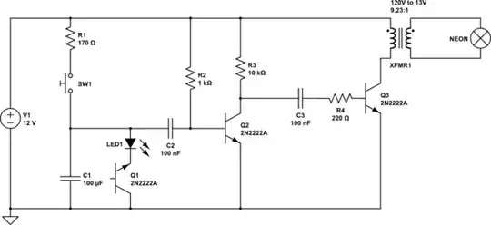
schematic

simulate this circuit – Schematic created using CircuitLab

Ryan Griggs
  • 2,596
  • 2
  • 30
  • 53
  • Where are you in this world that opamps are hard to source? – ThreePhaseEel Sep 02 '16 at 00:20
  • 1
    Sorry, I should have said "not in my junk box" haha. I have some on order from eBay but I was trying to make this out of as few discrete components as possible. (It's a learning experience!) :) I could have used a 555 to generate the pulses but wanted to learn how to build the simplest possible oscillator out of discretes. – Ryan Griggs Sep 02 '16 at 00:23
  • So if your primary criterion is "breadboard-friendly", why use the neon bulbs at all, rather than the much simpler to drive LEDs? – Dave Tweed Sep 02 '16 at 01:20
  • 1
    It is a learning exercise. Neon bulbs are cool. You can do unusual things like create oscillators etc with them. I want to demo these features safely on a breadboard and give other people the opportunity to try it also, with the simplest and least expensive/easiest to obtain parts. – Ryan Griggs Sep 02 '16 at 01:24
  • I think it's the DC aspect that causes just one electrode to glow. You might try a push/pull topology, or some kind of A/C. – MicroservicesOnDDD Nov 28 '20 at 21:43

1 Answers1

1

Two answers:-

  1. The output is floating so it's safer than the mains. It's like your shaver socket.
  2. You could buy something like a ready made HV psu It probably has less chance of exploding than a home brew device. It has both AC and DC outputs.

But another point I'd make is that solderless breadboards are small things for plugging LEDs into. The gaps between contacts are fairly small, and they won't be rated for 150V+. Plain vero board might be a better alternative.

I kinda asked something similar when I wanted to mess with some HV stuff here. There are some useful dimensions there in the answers.

Paul Uszak
  • 7,327
  • 5
  • 37
  • 69
  • Thanks for the link Paul. I definitely agree that protoboards are not suited for high voltages. When I tested this I spaced the HV connections far apart. However, I can't even get a *tiny* spark from this circuit if I touch the output wires directly together. Does that mean the output current is extremely low? I think these neon indicators have a turn-on voltage of about 90V, so I was hoping there was a solution "weak" enough to play with on solderless breadboards without safety concerns. :) – Ryan Griggs Sep 02 '16 at 01:44
  • I think that neons usually turn on (ignition) at about 140Vish. They then sustain conduction at a lower voltage, like 90V. I think that you're unlikely to get a spark from a 150V <1% duration pulses. You probably need either more current or more voltage. – Paul Uszak Sep 02 '16 at 02:01
  • I wouldn't be too concerned with the safety aspect of a simple circuit like this. Some here are just a bit soft when it comes to voltage. Don't forget that a cattle fence might be 8000V, and that just gives you a good kick. It's the current that kills you. – Paul Uszak Sep 02 '16 at 02:04
  • 1
    Here's a neat page on the current required to cause damage or be lethal: https://www.physics.ohio-state.edu/~p616/safety/fatal_current.html – Ryan Griggs Sep 02 '16 at 03:07
  • So, is the following output current calculation correct? Input to transformer: 12V / 100 ohm resistor = 120mA max input current. Transformer ratio: 9.23 : 1. Output current = 120mA / 9.23 = 13mA max at 110V? Did I miss something? – Ryan Griggs Sep 02 '16 at 03:14
  • Wired iron isn't my thing and others will be better placed to comment, but I would be extremely sceptical that it works like this. That's a standard mains step down transformer professionally designed and refined to operate at 60Hz pure sine wave. Irregular zaps of a <1% rectangular pulse will be very inefficient and totally outside of it's design parameters. If it were this simple, we'd all be building switch mode power supplies and they wouldn't be blowing up in our faces all the time. Just a feeling. Can your CircuitLab not do a simulation..? – Paul Uszak Sep 02 '16 at 10:01
  • @RyanGriggs -- An up to date for the [fatal_current.html](https://www.asc.ohio-state.edu/physics/p616/safety/fatal_current.html) web page. – MicroservicesOnDDD Nov 28 '20 at 21:25