0

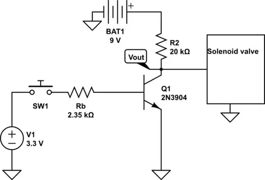
As a summer project I am trying to create an automatic irrigation system. To do so, I created a circuit with a single transistor which will move from saturation to off and thus behave as a switch.

schematic

simulate this circuit – Schematic created using CircuitLab

http://www.electronics-tutorials.ws/wp-content/uploads/2013/09/tran46.gif?81223b

After a few days struggling and learning, I successfully managed to make it work:

V1=0 ===> Vout=9v
V1=3.3v ===> Vout=0v 

The next step is to connect a 9v water solenoid valve to Vout and to earth, so that when V1=0 the valve opens and when V1=3.3v the valve closes. I tried the valve connecting it directly to the 9v battery and to earth and it works. However, when I connect it to Vout it does not work. I measured the voltage in Vout when it is 9v and as soon as I connect the valve, Vout drops to around 1v. What is happening? Is it perhaps that the valve is like a resistor and so I need to recalculate the value of the resistors?

M. Buil
  • 103
  • 4
  • 3
    Imagine if the transistor wasn't there - would your solenoid still work if it had that 20k resistor between it & the battery? Almost certainly not. Replace that resistor with the solenoid in your circuit. And I hope you made a typo with Rb - 2.35 ohms is *far* to low for a base resistor. – brhans Aug 31 '16 at 13:24
  • It is not a typo. I put 2 4,7K resistors in parallel. Currently, I only have 4.7K and 10K resistors. Is it too low to be a pull-up resistor? What would you put there and how could I know for other transistors? – M. Buil Aug 31 '16 at 15:06
  • 1
    You haven't labeled it **k**, just ohms. 2.35**k** is fine. And its not a pull-up resistor, is a base-current limiting resistor. – brhans Aug 31 '16 at 15:25
  • Oh! You are right, thanks! I have just edited it. I learnt about pull-up resistors here: http://www.seattlerobotics.org/encoder/mar97/basics.html and it says "Now consider the next schematic, which is similar to the first but has added a pull-up resistor. This resistors function is to limit the amount of current that can flow through the circuit" Is this wrong then? Thanks – M. Buil Aug 31 '16 at 15:37
  • In that case it is a pull-up because it pulls the input to the logic gate up when the switch is open (the switch acts as the 'pull-down' in that circuit). You're using it a little differently to that example. But this is just a minor terminology correction - nothing wrong with that part of your circuit. – brhans Aug 31 '16 at 16:14

2 Answers2

4

How much current does the solenoid require to open, and what is the part number??

Your circuit will not work. You are just shorted through the solenoid, as it's nothing more than a coil of wire.

In general, to drive a solenoid with a transistor, the solenoid needs to be in series with the collector (or emitter if the solenoid must be grounded, but it becomes a more complex issue). You have it in parallel. You should put in a resistor to limit current to no more than what the solenoid needs. Ballparking a 9V drop, if you need 100 mA, your resistor should be 90 ohms. This needs to be in series with the solenoid, and then they go to the collector. You will need a fast diode across the solenoid, reverse biased with respect to the supply, to avoid killing the transistor. Lastly, you should never let the transistor base "float" -- you should pull it to ground through a large resistor.

See http://www.edaboard.com/thread324980.html for a rough example http://www.edaboard.com/thread324980.html

That example does not have the resistor -- you may or may not need it, depending on the nature of the solenoid and transistor.

Scott Seidman
  • 29,274
  • 4
  • 44
  • 109
  • Thanks for the answer. I did not know about the diode, do I need it because of what is explained here: http://electronics.stackexchange.com/questions/31014/where-should-i-put-the-kickback-diode-in-a-transistor-switch I don't know the current that it needs, I asked the guy who sold it to me. I bought it here: http://www.aliexpress.com/snapshot/7511729801.html?orderId=74159973827216. Reading the specs of a similar solenoid, I found that it needs 240 mA. How would you create a supersmall resistor of only 36 ohms? – M. Buil Aug 31 '16 at 15:32
  • Another question if I may. The values of the resistors were calculated in order to saturate the transistor. If I remove the 20k resistor and add a 36 ohms resistor + the solenoid, I will need a 100 times smaller Rb, but that might be too small to be a current limiter resistor, right? What would you do? – M. Buil Aug 31 '16 at 16:12
0

The power required to activate a high pressure water solenoid will need more than a transistor and 9V battery. I expect the solenoid value <10 Ohms and you need a 100 milliOhm MOSFET.

The 9V battery might be able to supply the base current only but not activate 1 or more solenoids of low DCR.

It is imperative to define load voltage current and make the switch <<5% resistance or so less than the DCR of the solenoid to avoid heat heat rise.

  1. Define specs before you design.
  2. Test your assumptions afterwards
  3. Verify specs.
  4. Use reverse clamp diode across solenoid to protect driver from Turn off high V.
  5. Use a low side switch Nch between solenoid and V+
Tony Stewart EE75
  • 1
  • 3
  • 54
  • 182
  • Thanks. The battery is only connected to the collector. The 3.3V in the base come from a Raspberry Pi. When you mention MOSFET, do you imply that I cannot make it work with a BJT? I chose BJT because I am not looking for anything professional and as they are cheaper and the circuit is quite simple, a BJT would work for me. – M. Buil Aug 31 '16 at 15:44
  • for no heatsink, a logic level level FET is best, as depending on unknown DCR you may or may not not have enough current to drive base at 10% collector solenoid current . Base current should be 5-10% in assumptions – Tony Stewart EE75 Aug 31 '16 at 16:47