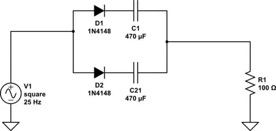
You can simulate the effect of a non-polar capacitor with polar capacitors and diodes, if you connect them correctly.
simulate this circuit – Schematic created using CircuitLab
As an AC voltage is applied across this combination, each diode will rectify, and charge up the centre node. The reverse voltage across either capacitor will not exceed one diode drop, which is probably OK for aluminium electrolytics.
Note that in use, the effective capacitance in this case is 500nF, the correct addition of two capacitors in series. I have seen people argue that each diode 'shorts out' its respective capacitor on each half cycle, and that the capacitance is therefore the value of just one capacitor. This is only true during the startup charging phase when the diodes conduct, the effective capacitance will be that of just one capacitor, 1uF.
If the pair has been exposed to one AC voltage for a while, so the centre node has charged to that voltage, and the voltage is suddenly increased, there will be a further phase of charging, and a change in effective capacitance while it charges.
If it's expected that the applied voltage will change, it's better to use a high value resistor to the centre node as well, to bias it to a higher voltage than either end will see. This will ensure that both capacitors stay correctly biassed for the whole time.