1

For a project, I like to feed a sine wave to laser, this sine wave must have a DC value of 2V and it should oscillate between 2.5 and 1.5V at 100KHz. The current required is <50mA.

What is the best way to achieve this configuration?

UPDATE What Olin described below is simple and elegant, probably works well. I have three bonus questions.

  1. If I wanted to add a feedback fromt the photodiode inside the laser module to optimize the light output, how can I do that? (I am guessing some sort of feedback from PD to the + terminal of the Opamp for modifying the DC bias).

  2. If I wanted less harmonic content, could I use an active BP filter that is narrow on the target frequency (100KHz etc) before the driver?

  3. If I want a higher frequency the limiting factor would be the GBP of the opamp?

Ktc
  • 2,226
  • 3
  • 26
  • 48
  • 1
    possible duplicate of [Driving an LED/Laser diode with a RF signal up to 20 MHz](http://electronics.stackexchange.com/questions/24516/driving-an-led-laser-diode-with-a-rf-signal-up-to-20-mhz) – Olin Lathrop Jan 20 '12 at 17:02
  • 1
    Not duplicate. Previous question wanted higher modulation current and much higher frequency. Solution to this question can be much simpler. – The Photon Jan 20 '12 at 17:08
  • @user3685, in the world of low-power semiconductor lasers (you are talking about a diode laser, not a HeNe or something, right?) 100 kHz is practically DC. What have you tried, and why don't you think it will work? – The Photon Jan 20 '12 at 17:10
  • 1
    It's still basically the same thing with the same answers applying. The main issue with both these is that they want to modulate the laser linearly and not just on/off. – Olin Lathrop Jan 20 '12 at 18:32
  • Except that for a laser at 100 kHz, there's no special need to use extra care to drive the load in both directions, as all the solutions to the prior question did. – The Photon Jan 20 '12 at 21:47
  • @OlinLathrop your previous solution assumes we have a AC source available, I don't have one. I need to generate this AC source and than I can use your voltage controlled current sink approach. I only have a uP that can emit a 100KHz squarewave. – Ktc Jan 21 '12 at 04:52
  • @user3685, Typically you'd want to drive the laser with a certain amount of current, and let the voltage adjust itself as necessary. Using a fixed voltage source (like the 2.5 to 1.5 V you specified) risks damaging the laser. Can you explain why you want your signal to have those certain voltages? – The Photon Jan 21 '12 at 06:45
  • @ThePhoton I plan to use this as the voltage rail and have a limiting resistor. The voltage drop of these lasers are generally constant and having a limiting resistor helps me to tune the curent passing through. – Ktc Jan 21 '12 at 08:09
  • Well, you have two problems: 1. Convert a square wave into a sine wave. All you need is a low pass filter, but the details of the filter depend on how much distortion is allowable in the sine waveform. 2. Translate that sine wave to the voltage or current levels you want. For reliability of your laser, I would still recommend using a current driver rather than a voltage driver and limiting resistor...but your way would likely work also. – The Photon Jan 21 '12 at 16:52
  • @ThePhoton can you explain me how I can make a current driver? – Ktc Jan 21 '12 at 17:00
  • Now that I answered here, I found two better candidates for duplicate or at least overlapping questions: 1. http://electronics.stackexchange.com/questions/17784/laser-driver-circuit and 2. http://electronics.stackexchange.com/questions/10082/why-is-a-laser-supply-so-tricky – The Photon Jan 21 '12 at 22:53
  • I have withdrawn my answer -- with optical feedback, Olin's ac coupling scheme is safer in terms of overcurrent when the modulation source is turned off and on. – The Photon Jan 22 '12 at 11:33

2 Answers2

6

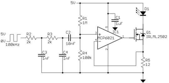
As I understand it, you want to drive a laser diode with a 100 kHz sine wave with a bias of about 40 mA. The 100 kHz signal is is available from a 0-5 Volt digital output. Here is a circuit that should at least be a reasonable topology:

You will have to fill in the right values yourself. The ones I show represent only a very rough stab at it.

R2, C3, R3, C4 are a two pole low pass filter. This will eliminate much of the harmonic content of the 100 kHz square wave to make it closer to a sine wave. In this scheme more filtering also reduces the amplitude, so you will have to change R5 if you adjust the aggressiveness of the filter. R1 and R4 set the DC bias. In this example is should be roughly 40 mA. C2 AC couples the signal from the filter to the opamp while leaving the average bias alone. The feedback circuit makes sure that this composite voltage (AC signal plus DC bias) appears accross R5. This regulates the diode current since the current thru R5 is the same as the current thru the diode.

Note that this never explicitly sets the diode voltage. Rather, it regulates the current thru it. That's a much better way to drive a LED or laser diode than trying to fix its voltage. This circuit will automatically make the voltage as needed to get the desired current.

Again, you will likely have to adjust the values. You never said how much harmonic content you can tolerate, for one.

Added in response to your two questions:

The FET acts like a variable resistance. It is varied by the opamp to make sure that the input signal (opamp pin 3) appears accross the output current sense resistor (R5). Since the current thru R5 and D1 are the same, and the voltage accross a resistor is proportionaly to the current thru it, the voltage at the top end of R5 is proportional to the diode current.

This circuit would still work somewhat without the opamp, but not as accurately. The opamp drives the gate of Q1 to whatever it takes to get the desired diode current. The gate to source voltage of Q1 will vary with current. This voltage offset is automatically compensated for by the opamp since it is inside the feedback loop. The exact gate-source voltage required for a particular current is poorly specified and will vary from device to device and over temperature. By regulating the voltage on R5 instead of the voltage on the gate of Q1, the gate-source voltage is automatically compensated for by the opamp and becomes irrelevant. Actually, it's only irrelevant as long as the required gate voltage is within the range the opamp can put out. The IRLML2502 has a low enough gate-source turn on voltage so that this is guaranteed to be true. We don't know exactly what that voltage is, but we do know it will be well within the 5V output range of the opamp.

Using the built-in photodiode to regulate the laser's actual light output is even better than regulating its current. In that case you have to add a circuit that creates a voltage proportional to the laser light output, then feed that into the opamp negative input instead of the of R5 voltage. The opamp will then drive Q1 to whatever it takes to achieve the light output proportional to the input signal.

Olin Lathrop
  • 310,974
  • 36
  • 428
  • 915
  • thanks very much.. I can see how this circuit works now, very simple and elegant. If I wanted to add a feedback from the internal Photodiode of the Laser, how would I do this in this configuration? – Ktc Jan 22 '12 at 03:06
  • 1
    what is the purpose of the mosfet? I simulated the circuit without the mosfet and it still works. I couldn't quite figure it out. – Ktc Jan 22 '12 at 03:54
  • @Ktc, the output current of the [MCP6021](http://ww1.microchip.com/downloads/en/devicedoc/20001685e.pdf) is +/-22mA at +5.5vdd (and trying to drive an op-amp to max \$I_{SC}\$ would likely distort the output badly.) *Also* the op-amp voltage out into a MOSFET creates a simple *current* driver. The MOSFET can sink/source much more current. – rdtsc Oct 24 '18 at 00:05
3

The MOSFET gives current drive capacity. The op amp may simulate in Spice as able to provide unlimited current but probably not in practice. The feedback takes care of removing MOSFET nonlinearity as well. Since this is a depletion mode MOSFET \$ID = K \cdot (V_g-V_{th})^2\$ where \$V_g\$ is gate voltage, \$V_{th}\$ is the threshold where current flow starts and \$K\$ is related to the FET geometry. \$K\$ can be calculated from the datasheet. As you see \$ID\$ is nonlinear.

Ricardo
  • 6,134
  • 19
  • 52
  • 85
lb3hc
  • 31
  • 1
  • 1
    Welcome to EE.SE. This looks like a comment to one of the comments for the previous answer. Since it doesn't answer the question directly it should be a comment. Once you have earned 50 reputation you will be able to comment everywhere. – Null Dec 09 '14 at 19:14