There are two ways to approach this question.
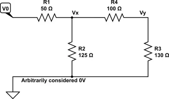
a) The first is to use the voltage divider rule twice
Put R3 and R4 in series
Combine those in parallel with R2
This now forms the load on R1
So now compute the voltage on the R1-R4 junction
Now compute the voltage on the R4-R3 junction
b) The second is to use the Y-Delta transformation
Make the Y (or Wye, or Star) of R1, R2 and R4 into an equivalent Delta of three resistors. Let's call those resistors Ra, Rb and Rd (1st, 2nd and 4th letter of alphabet, opposite the corresponding Y resistor).
simulate this circuit – Schematic created using CircuitLab
Now Rd is across the source, and doesn't take any part in the sums.
Ra is in parallel with R3, you must combine them to get the proper load on Rb.
Now use the voltage divider formula with Rb feeding the load of Ra||R3.
I've not calculated the values of Ra, b and d, you can do that from the formulae on wikipedia, search for 'wye-delta'.
Which is better?
They give the same answer.
The extra computation needed for Y-delta is probably more than for two applications of the voltage divider rule.
I can remember and check the voltage divider rule, but I need to look up the Y-delta formulae.
With ladder structures, you can always extend the first method.
With lattice or bridge structures, you may need the second method.