43

I want to add a real time clock module into my little project. I want to display both time and date on my existing i2c 2x16 LCD module.

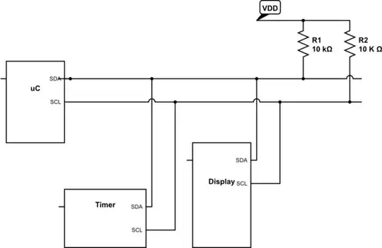
Both i2c-interface real time clock module and 2x16 LCD module use the same pin A4 (SDA) and A5 (SCL) on Arduino Uno. After hours of searching on the net the i2c bus can actually take many serial devices. This is possible because each device has its own unique address.

My question is how to physically wire the two i2c-interface devices into a single A4 and A5? Thanks.

banksia
  • 431
  • 1
  • 4
  • 3
  • 4
    Short answer: Wire them in parallel. Tie the SDAs together and connect to A4, and the SCLs to A5. Then of course there is the pull-up issue that sometimes helps. – SDsolar Mar 23 '17 at 06:20

6 Answers6

39

Some folks are having a hard time visualizing things connected together, so here's a picture:

(Serving suggestion)

schematic

simulate this circuit – Schematic created using CircuitLab I2C is a bus, so like-named signals are connected together. The addressing scheme allows the microcontroller to select which device it's talking to. On the Arduino, the 10kΩ pull-up resistors go to VDD (Usually +5V or +3.3V).

CATboardBETA
  • 223
  • 2
  • 11
gbarry
  • 8,615
  • 21
  • 31
  • 2
    Hi, this may be very basic but I am new to electronics and landed this page from google search , what uC refers to ? – Ciasto piekarz Nov 30 '16 at 07:06
  • I believe the reference is to any uC, as the connection scheme should be the same, unless noted otherwise. – KingsInnerSoul Jan 05 '17 at 01:29
  • 1
    uC can be an Arduino. SDA is pin A4 and SCL is pin A5. – SDsolar Mar 23 '17 at 06:21
  • 16
    @Ciastopiekarz, μC is short for "microcontroller." The greek letter μ is the abbreviation for micro. Because μ looks like u, lots of people just write "uC". – foobarbecue Jul 23 '17 at 01:17
  • I2C is a 2-wire "shared" serial bus that means that you connect all the SCL clock lines together and all the SDA data together by wires or traces. Electrically, this is okay because each I2C chip added on the bus has open-collector input/output I/O pins that allow being wired together. At least 1 I2C pull-up resistor is required for each of the SCL or SDA lines so the signal can switch hi/low fully. Typically, 2.2K to 4.7K ohms are used but 10K may work, too. – Will Patton Sep 23 '20 at 22:46
12

For I2C, if all the slave devices have different device addresses, all of the SDA pins should be connected together, and all of the SCL pins should be connected together. It's as simple as that.

Naturally, you should also include pull-up resistors on both lines, as required for I2C. How to choose the resistor values has been discussed here before.

SamGibson
  • 17,231
  • 5
  • 37
  • 58
The Photon
  • 126,425
  • 3
  • 159
  • 304
  • I've found that as long as one of the devices is the DS3231 RTC then no external pullups are required. – SDsolar Mar 22 '17 at 21:15
  • 3
    @SDsolar, that probably means the DS3231 has internal pull-ups, so by using that device, you are providing pull-ups for the bus. That's not necessarily a good thing, because it limits your freedom to adjust the pull up resistance depending on the number of devices on the bus. – The Photon Mar 22 '17 at 21:45
  • My thoughts exactly. Adding external pullups would be in parallel with whatever is in the DS3231, and so might end up not being enough for I2C to be happy. – SDsolar Mar 23 '17 at 05:49
  • @SDsolar, What does this have to do with OP's question or my answer? This is not a general discussion site. If you want to just talk about stuff, you can join our [chat room](http://chat.stackexchange.com/rooms/15/electrical-engineering). – The Photon Mar 23 '17 at 15:43
  • @CATboardBETA - Hi, FYI I'm reversing your last edit here, as (a) the I2C terms you used are not the official new ones, and (b) In any case, we are working on a plan for the whole site about how to handle the changes to I2C terminology. That plan will apply to everyone - so we can't have individual members going around editing that I2C terminology, until that discussion has happened on Meta. Therefore please do not make any more edits for I2C terminology until after that discussion. (That post was planned to happen sooner on Meta, but it's been interrupted by other moderation work.) – SamGibson Jan 13 '22 at 06:33
3

Connect two pins A4-sda to A5-scl(on both board uno-uno) and connect resistor from 5v from each corresponding sda-scl lines.

enter image description here

1

I2C is a data transfer protocol developed by Philips. Also known as two-wire interface since it uses two wires for communication. SCL-Serial Clock Line. SDL-Serial Data Line. So you need to connect corresponding pins of the i2c devices be it an eeprom or lcd to SCL and SDL pins of micro controller you are using with a pullup resistor to VDD. Since it is an addresses protocol having 7-bit address for each device connected you can address upto 2^7 different devices. But normally I2C address of a slave device is predefined with some bits to be hardwired by the developer. This helps in connecting same type of devices with different hardwired address part on the same bus.

Moogblob
  • 3
  • 1
  • 1
    All true, but it sucks if you want more than one, like the BH1750 light-intensity unit. I want 4 of them and don't want to deal with I2C dual-bus switching.. Also, some devices like the DS3231 have internal pullups so any external pullups are in parallel with them. – SDsolar Mar 23 '17 at 06:14
1

Also you should check the pull up resistors. If you use already made boards, not only the chip, that boards usually have pull up resistors on board between buss and vcc. So when you connect every thing in parallel, the resistors are also in parallel, so total resistor value drop and your communication may fail.

Petre O.
  • 11
  • 1
1

Another thing to keep in mind is as the number of devices grows, the capacitance of the clock and data lines will increase. At a certain point, the C component increase will affect the rise times of your clock. Unless you are clock stretching, you can make the clock strong drive or put a stronger pull-up on it to avoid this.

cplusruss
  • 85
  • 3
  • Not really. At all times the capacitance affects the rise time. So it does not start affecting the rise time until after certain point. Stronger clock drive does not affect rise time on an open collector bus, only the pull-ups. Clock stretching is rarely used and even if it is it typically is done after each byte, not each bit, so it does not help. – Justme Aug 18 '23 at 16:54