2

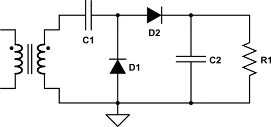
I am not fully sure as to how this circuit works. I know that during the positive half cycle D1 is on and C1 charges to V volts, and that during the negative half cycle D1 will become off and D2 conduct. So some charge flows from C1 to C2, keeping C2's voltage at some level until the next negative half cycle. But how will the voltage across C2 end up being at ~2V volts at the end?

schematic

simulate this circuit – Schematic created using CircuitLab

Edit: D1 is on when it's negative half cycle and off when positive. I knew this.

MicroservicesOnDDD
  • 2,557
  • 1
  • 13
  • 48
dirac16
  • 1,774
  • 2
  • 12
  • 17
  • 1
    I think that during the NEGATIVE cycle D1 is on and charges C1 to approximately the negative peak voltage (with the more + voltage on the cathode of D1.) Then during the positive cycle the charge from C1 charges C2 to the positive peak voltage plus the voltage stored on C1. – John D Aug 11 '16 at 21:41
  • @John D I understand most of this circuit but don't the last line. Could you explain how the voltage stored on C1(if there is any after its charge moved to C2) adds up to C2 to form 2V volts across C2? – dirac16 Aug 11 '16 at 22:42

1 Answers1

2

During the negative half cycle D1 is on and charges C1 to the negative peak voltage minus the diode drop (with the more + voltage on the cathode of D1.)

Then during the positive cycle the charge from C1 transfers to C2. The voltage delta on C2 will depend on the relative size of the capacitors, but with no or light load the "buckets" of charge from C1 will eventually fill C2 to twice the input voltage minus diode drops and resistive losses.

[ If the voltage on C2 is less than 2X Vin then charge will flow from C1 to C2 since C2 is charged to the negative peak of the input sine wave each cycle. On the positive cycle C1 is "lifted" to ride on top of the positive half of the sine wave creating a current that charges C2. Once C2 reaches ~2X Vin, C1 can no longer transfer charge to the output, so the output stays at that level. ]

If the energy removed by the load is less than the energy transferred each cycle, the output will still eventually ramp up to close to 2X the input voltage.

John D
  • 22,677
  • 1
  • 39
  • 56
  • That's 2x 'the peak-to-ground voltage', rather than 'the input voltage'. Conventionally. all AC voltages are RMS-measured. It's circa 2.8 times the RMS input that shows up on C2. – Whit3rd Aug 12 '16 at 01:30
  • Thanks @John D for further clarification. I understand except the way C2 charges. In order the charge to move to C2 shouldn't we have a loop so that charges could pass from C1 all the way to C2? – dirac16 Aug 12 '16 at 16:08
  • @Whit3rd Excellent point, exactly right. To the OP: Not sure what you mean by a "loop so that charges can pass". If it helps, forget C1 is a capacitor and think of it as a voltage source of value Vin peak. When the secondary voltage plus the voltage source voltage rises above the output voltage (plus diode drop) D2 turns on and current flows into C2, right? It's similar with a capacitor, but the amount of charge transferred is limited during each cycle. – John D Aug 12 '16 at 16:28
  • I think I got it. Using kvl when D2 turns on I have for Vout: Vout=Vmax(of voltage source)+Vin peak(of C1) - diodes' drop. Am I right? – dirac16 Aug 12 '16 at 16:50
  • Yes, that's correct! – John D Aug 12 '16 at 17:35