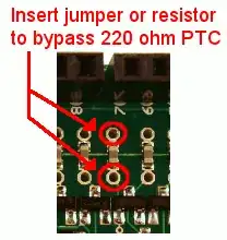
While using a logic analyzer with analog voltage to test Digital Output Pin voltages on an Arduino UNO, I am seeing the expected digital output and analog output (HIGHs and LOWs for digital and 5V to approx. 0V for Analog).
I'm using a Saleae logic 4 to test the digital output of an Arduino and an Arduino-compatible (Ruggeduino) for simple digital output. The Arduino seems to run my sketch just fine and the Saleae can read my output pin as both digital and analog. The moment, however, I drop the "Ruggeduino" in with the same sketch, my digital output seems to fail to work, and when I take another sample with the Saleae, my "Analog" voltage shows the highs and low voltages I'm expecting, but the "Digital" output is suspiciously blank.
Why would my logic analyzer show the expected digital and analog output when testing the Arduino Uno, but show a consistent "High" for digital output but both high and low voltages on the Analog output when testing the Ruggeduino?
Additional Information: Devices used:
Edit: Not satisfied to just sit and wait for someone to answer, I did some more digging. Here's what I found out:
- The logic appears "High" despite the change in voltage, looking as if it's stuck High
- The Analog voltage of "Low" for the output pins appears to be 1.586V, which falls outside the range of TTL "LOW" (and most likely the cause of the "stuck" logic level)
- This only happens when the pins are connected to the downstream input pins that should only be listening for digital output. Once you remove the downstream pins from the equation, the "LOW" voltage drops back down to just above 0V.
I don't currently have a screenshot handy to upload, but I can upload my sketch to show what I'm attempting to do:
void writeWiegand(String);
int outZeroPin = 6;
int outOnePin = 7;
int led = 13;


void setup() {
  pinMode(outZeroPin, OUTPUT);
  digitalWrite(outZeroPin, HIGH);
  pinMode(outOnePin, OUTPUT);
  digitalWrite(outOnePin, HIGH);
  Serial.begin(9600);
  delay(1000);

}


void loop() {
  String code = "0001001001100101100000001011010010";
  writeWiegand(code);
  delay(500);


}

void writeWiegand(String code) {
  for (int i = 0; i <= (code.length() - 1); i++) {

    if (code.charAt(i) == '0') {
      digitalWrite(outZeroPin, LOW);
      //delayMicroseconds(100);
      delay(100);
      digitalWrite(outZeroPin, HIGH);
      Serial.print(code.charAt(i));
    } else {
      digitalWrite(outOnePin, LOW);
      //delayMicroseconds(100);
      delay(100);
      digitalWrite(outOnePin, HIGH);
      Serial.print(code.charAt(i));
    }
    //delayMicroseconds(100);
    delay(100);
  }
  digitalWrite(led, LOW);
  Serial.println(" Output to Wiegand");
}
Edit 2: The downstream device is a proprietary Access Control Panel, and the input pins are pins are for Wiegand communication with a card reader. Since it is proprietary, I'm not sure what I'm legally allowed to share. According to the manufacturer, the two input pins output 5V which the reader is supposed to Pull to ground to send information on either the "Zero" or "One" wire. The UNO R3 works fine for this task with the same code above. When pulling low with the Ruggeduino, there is still 1.586V left over, which I find confusing.

