2

I got an old washing machine motor (universal) laying around that I'd like to speed control. I'm new to almost all the components mentioned above, but here is what I currently use:

  • Microcontroller: Arduino Nano
  • Optoisolator: MOC3041
  • TRIAC: 2N6071AB (Replace? Thinking of BTA24-600B)
  • Universal Motor: UOZ 112 G 55

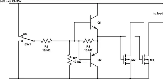
After a long search I came across this circuit:

enter image description here

First off, I tried to hook the TRIAC (2N6073AB) to 240 VAC. It scattered into two pieces after about 5 sec. It says it's meant for 400 VAC, so I'm a bit confused. I didn't have a heat sink attached though, but still. Can someone explain this behaviour?

This is how I connected the TRAIC for testing purposes:

schematic

simulate this circuit – Schematic created using CircuitLab

For the circuit above, I bought 1/4 watt resistors. I cannot understand how they can handle 240 VAC, seems really strange to me. Maybe they can't. Like the capacitor in series with the 39 ohm resistor. How is that even possible?

What role does the 330 ohm resistor play, why is this one needed? It also says "for highly inductive loads, change this value to 360 ohms." What value? Is it the 39 ohm resistor? Why change it, is it because of the high start current for motors?

For the 0.01 microfarad capacitor, where does this value come from? From what I've softly read, the snubber circuit is to prevent the phase shift between voltage and current caused by the motor, right? Will these capacitors do: blue ceramic disc capacitors 1KV 1000V 103PF 0.01uF?

I've been reading some PDFs about thyristors (including TRIACs,) and it said:

"The output of most microcomputer input/output (I/O) ports is a TTL signal capable of driving several TTL gates. This is insufficient to drive a zero-crossing TRIAC driver."

I guess that's not the case with Arduino Nano since it uses a PWM signal. Do I still need the NAND-gate? If someone would like to explain why the zero-crossing TRIAC driver doesn't accept certain signals, I would be grateful.

JRE
  • 67,678
  • 8
  • 104
  • 179
MrMongoloid
  • 81
  • 1
  • 2
  • 8
  • Pop the motor details into the question (rather than spread through the comments) so that all the relevant info is there. +1 for a very well written first question. – Transistor Jul 31 '16 at 18:49
  • 1
    Controlling a Universal motor this way won't do quite what you expect. You'll need to separate its field and rotor windings, and keep the field winding connected to the full supply voltage (assuming it's shunt wound). Otherwise the speedup (from field reduction) and slowdown (from rotor voltage reduction) will cancel out. –  Jul 31 '16 at 18:58
  • @Brian Drummond Universal motors are series wound by definition. –  Jul 31 '16 at 19:06
  • Are you certain the motor is a universal motor? –  Jul 31 '16 at 19:07
  • @Brian Drummond, Very interesting. I need to take a closer look at your suggestion. So you mean it wont work at all, or just behave in at very unpredictable way? – MrMongoloid Jul 31 '16 at 19:44
  • @Charles Cowie, I'm not certain, but I think so. It got brushes ect. It's not an induction motor, but what else could it be? – MrMongoloid Jul 31 '16 at 19:44
  • If it has a commutator and brushes, it is a universal motor. I found a little information online that seems to confirm it is a universal motor. I think the motor should work fine with the proposed control scheme. Brian Drummond was only warning about shunt connected motors, since a universal motor is series wound, what he said doesn't apply. If it were shunt wound, it wouldn't work at all with AC power. –  Jul 31 '16 at 20:14
  • Alright, thanks for clearing this out. I can add that I've tried the motor directly on the 240 VAC power supply, and it seems to work just fine. Also the RPM kept increasing over time. – MrMongoloid Jul 31 '16 at 20:29
  • Universal motors are very sensitive to load. If you take one out of a machine, and operate it without anything connected to the shaft, it will run very fast. The speed is only limited by the friction of the brushes and bearings plus the air drag on the moving parts. It is possible that heating the air and lubricant reduces the load sufficiently to allow the motor to speed up over time. –  Jul 31 '16 at 21:26
  • 1
    @CharlesCowie "if it were shunt wound, it wouldn't work at all with AC power" what stops it working with AC? Both rotor and field reverse polarity at the same time, just as in the series form. Is it the phase shift as the field winding is almost purely inductive? –  Jul 31 '16 at 21:28
  • 1
    I believe the R/L would need to be much different because the armature and field would need to be designed to operate at the same voltage but draw much different currents. Also, the back emf controls the armature current. Those two things would cause a phase difference between the armature and field. With a series motor, there is only one current path and thus no possibility of phase difference. –  Jul 31 '16 at 22:03
  • @CharlesCowie Thanks! I read that as, shunt might possibly work, but probably inefficiently, while series thanks to one current path, is just much easier to get right. And that makes series the universally adopted strategy. –  Aug 01 '16 at 10:19

1 Answers1

3
  1. So first off; I've tried to hook the TRIAC (2N6073AB) to 240 VAC, it scattered into two pieces after about 5 sec.

Without a schematic of your wiring we can't say. It sounds as though you mis-wired it or switched it on to a dead-short between mains and neutral. There's a schematic button on the editor toolbar if you wish to update your question.

  1. For the circuit above, I bought 1/4 watt resistors, and I cannot understand how they can handle 240 VAC, seems really strange to me. Or maybe they can't? Like the capacitor in series with the 39 ohm resistor, how is that even possible?

enter image description here

Figure 1. Carbon film resistor with exposed carbon spiral (Tesla TR-212 1 kΩ). Source: Wikipedia Resistor.

There are three main specifications to watch when using resistors:

  • The resistance value. This is obvious.
  • The voltage rating. In Figure 1 we can see a spiral resistance track around a ceramic core. The track is probably about 20 to 25 mm long if unwound. Above a certain voltage electrical breakdown will occur across the resistor - perhaps jumping between turns on the spiral. Typically they're good to 200 to 250 V but mains voltage can peak at \$ \sqrt {2} V_{RMS}\$ so when we use them on 230 V mains we generally use two in series.
  • The power dissipation has to be kept below the rating of the resistor. This can be checked using \$ P = \frac {V^2}{R} \$ or \$ P = I^2R \$.

It may help to consider capacitors as two layers of foil separated by an insulating film. All that is required is to make the insulation layer thick enough to withstand the applied voltage.

  1. What role does the 330 ohm resistor play, why is this one needed? And it also says "for highly inductive loads, change this value to 360 ohms", what value? Is it the 39 ohm resistor? And why change it, is because of the high start current for motors?

There are three resistors in your circuit.

  1. For the 0.01 microFarrad capacitor, where does this value come from? And from what I've softly read, the snubber circuit is to prevent the phase shift between voltage and current caused by the motor, right? Will these capacitors do: Blue Ceramic Disc Capacitors 1KV 1000V 103PF 0.01uF?

Covered above. I don't know what the 103PF means. The Littlefuse article should give you enough detail on this.

  1. "The output of most microcomputer input/output (I/O) ports is a TTL signal capable of driving several TTL gates. This is insufficient to drive a zero-crossing TRIAC driver."

You don't quote a source for this but it looks a bit out of date. Most of the micros can now switch 20 mA and this is plenty for an opto-isolator LED.

  1. I guess that's not the case with Arduino Nano since it uses PWM signal? Or do I still need the NAND-gate? And if someone would like to explain why the zero-crossing TRIAC driver doesn't accept certain signals, I would be grateful.

PWM isn't used with triac control circuits. This is explained in my answer to Activating SSR for an AC motor via PWM input.

Further reading:

ON Semiconductor's 240 page Thyristor Theory and Design Considerations Handbook is a very in-depth look at the topic but is fairly readable if you pick an aspect of interest.

Transistor
  • 168,990
  • 12
  • 186
  • 385
  • Thanks for your indepth answer. It was very helpful, but I haven't had time to take a closer look at it yet, but I sure will! "It sounds as though you mis-wired it or switched it on to a dead-short between mains and neutral." - Well, I was afraid of damaging the MOC3041 and the microcontroller, so I wanted to test the TRIAC first. But here is how I connected it: http://i.stack.imgur.com/UWvPV.png – MrMongoloid Jul 31 '16 at 19:58
  • I also want to add that I am truely grateful for all your links as well, I'm most certanly gonna read them. As I found it rather difficult to find good reading materials myself. – MrMongoloid Jul 31 '16 at 20:03
  • The connection looks OK but there's no trigger circuit shown. By the way, there's a schematic button on the editor toolbar and it embeds editable schematics into your post. – Transistor Jul 31 '16 at 20:07
  • "(...) but there's no trigger circuit shown", I didn't get that far with my experimenting, but I was going to use the circuit that I briefly mentioned in my topic: http://imgur.com/d9nEwLQ. Without the snubber circuit though, as I thought this wasn't as important. Let me know if I misunderstood you. – MrMongoloid Jul 31 '16 at 20:23
  • OK. Double-check your triac pin-out. – Transistor Jul 31 '16 at 20:27
  • According to the datasheet I've used, there was no error in my connection. – MrMongoloid Aug 01 '16 at 10:53
  • "Typically they're good to 200 to 250 V but mains voltage can peak at 2√VRMS so when we use them on 230 V mains we generally use two in series." - Why does this make the resistors better suitable to withstand the high voltage? – MrMongoloid Aug 01 '16 at 18:18
  • \$ 230 \sqrt {2} = 325~V \$ and that's too much for one resistor. If we use two resistors in series, each of half of the desired value, then each one will only have 325/2 V = 162 V across each one and that will be safe. – Transistor Aug 01 '16 at 21:04
  • Yes, of course. I was being silly... I guess I could also connect two resistors in parallel to decrease the amount of watt generated in each resistor. – MrMongoloid Aug 02 '16 at 11:18
  • No, not in parallel. That would give the full voltage across both. Connect in series to reduce voltage (and power) on each to half. – Transistor Aug 02 '16 at 11:21
  • Hmm, doesn't the current get reduced by 50% if I connect them in parallel, as I also has to double the amount of resistance in each resistor? But yes, I can see that connecting them in series also reduces the power. – MrMongoloid Aug 02 '16 at 11:27
  • I also read one of your answers, where you were talking about "On-off AC time control" and "Phase-angle control". And to be honest, was I going for the "On-off AC time control". But because you made your point concerning motor control applications, I might as well go for the "Phase-angle control". I've been reading some about phase-angle control lately, and if I'm not mistaken, I need a way to meassure the zero crossing voltage with the microcontroller. Could I use this very simple circuit to do so: http://imgur.com/a/VK4AB? In either case, I'd like to hear your opinion. – MrMongoloid Aug 02 '16 at 11:55
  • (1) "_... doesn't the current get reduced by 50% if I connect them in parallel?_" Yes but they get the full _voltage_ across each. If that's within the specification of the resistor that's fine. (2) You will find many questions on zero-cross detection on this site. That one is almost OK. The peak voltage out of it will be \$ \sqrt {2} \$ times the transformer voltage so you'll need to protect the micro-controller input. – Transistor Aug 02 '16 at 14:52
  • Alright, a last quick question: Does a opto-isolator with zero crossing circuit (like MOC3041) prevent phase-angle control? To my understand it seems so. – MrMongoloid Aug 03 '16 at 09:31
  • Yes. That was explained in detail in the linked answers. – Transistor Aug 03 '16 at 09:33