3

I have a H-bridge IC L293DNE that needs 5V input signals to operate, however my available outputs are only 1.8V from a Gumstix Overo GPIO pin. I have a power supply that supplies me with +5V 1A. I've searched around for information about "Level Shifters" and "Logic Level Translation", but have been unable to find any good basic information.

I have a few 2N2222 transistors laying around, and I need to convert four 1.8V outputs to 5V, but I have no idea how the circuit should work. Will the 2N2222 do? Do I need resistors, and if so, where do I put them and how do I calculate the resistance needed?

AndrejaKo
  • 23,261
  • 25
  • 110
  • 186
jfax
  • 137
  • 2
  • 8
  • 1
    possible duplicate of [Bi-Directional Step up and Step down (3.3v <-> 5, etc)](http://electronics.stackexchange.com/questions/622/bi-directional-step-up-and-step-down-3-3v-5-etc) – Brian Carlton Jan 11 '12 at 00:50
  • 1
    or http://electronics.stackexchange.com/questions/24111/3-3v-to-5v-translation – Kellenjb Jan 11 '12 at 02:03
  • 1
    Similar to prior questionsbu enough differences to make it a useful addition. While the while set of questions and answers could be put together as a greater structured whole, it's unlikely to happen any time soon. – Russell McMahon Jan 11 '12 at 05:53
  • or "Level Shifting 1.8V to 5V with N-channel FET": http://electronics.stackexchange.com/questions/24011/level-shifting-1-8v-to-5v-with-n-channel-fet/24028#24028 – Curd Jan 11 '12 at 23:33

2 Answers2

7

(1) Try this (magic :-)

Use 2N2222 + 2 x 10k resistor.

When input is low transistor is on and output is pulled low.
When input is high transistor is off and output is pulled high by collector resistor.

This is a less usual arrangement but allows non-inverted switching - in highh = out high etc.

enter image description here

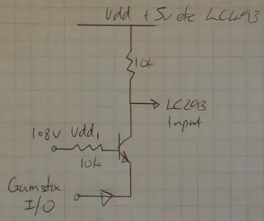
Gumstix output has to provide LC293 input current and Vdd/10k input current as well. Should be no problem. Collector resistor MAY not be needed depending on LC293 behaviour.

Added:

MOSFETS:

If you use low Vgsth MOSFETS instead of transistors you can remove the input resistors. As above, the LC293 inputs MAY float high when open circuit - alowing the collector resistor to be eliminated - but even if they do it may not be something you should depend on.


(2) This uses no transistor but may need component cvalue adjustment to work acceptably.

2k7 LC293 input to 5V
2k2 LC293 input to ground

LC293 input is now at 2.25V.
This is a valid high input.

Connect a silicon diode from LC293 input to Gumstix output (arrow points to Gumstix, or Anode to LC293 cathode to Gumstix)

Connect a 100k from Gumstix output to ground (more conceptual than actual)

Set Gumstix output to 1.8V.

Diode Cathode and Gumstix output now "want to be" at 1 diode drop ~= 0.6V below 293 input = 2.25 - 0.6 = 1.65V. ie the diode means the 293 input is hardly if at all affected when Gumstix output ii 1.8V.

Now drive Gimstix out to 0V.
LC293 input is now at about 0.6V.
The data sheet does not make it certain but this will probably turn the LC293 input off.

Check voltages in above to ensure no voltages exceed IC ratings.


Russell McMahon
  • 147,325
  • 18
  • 210
  • 386
  • +1 for common-base magic. Most of the other offered circuits invert the signal. – markrages Jan 11 '12 at 02:40
  • Your schematic is reasonable, but you accidentally flipped the description around in how it works immediately above the schematic. *High* input turns transistor on, which makes output go low. – Olin Lathrop Jan 11 '12 at 12:44
  • @OlinLathrop - the text is correct as it reads now. The driver is intentionally non inverting. Someone may have edited my text but I thought that was how I wrote it. The point which I could have made clearer is that the transistor is in common base mode with the emitter driven as the input so it doesn't invert. [[I know you are fully aware of this method so either my diagram is not clear enough or my text has been edited. (or both :-) ) ]. – Russell McMahon Jan 11 '12 at 12:52
  • Ah, so that triangle in what I thought was a misplaced ground symbol means something else, and the base connection is intended to go to a fixed supply voltage apparently. Since it said 108V and that made no sense, it looked like that was meant to be the input signal. Maybe that was meant to be "1.8V"?. I see now this is a common base and therefore doesn't invert. The only drawback is that the low level isn't that low. As long as the minimum high threshold for the 5V device is high enough that's OK. – Olin Lathrop Jan 11 '12 at 13:28
  • @OlinLathrop - Low should be reasonable - probably in the 0.1V - 0.2V range I think. Resistor in base circuit allows base to float downwards to a Vbe above emitter. If emitter is driven to ground then Vb will be say 0.6V Volts-ish and Vc can fall to below Vc so to about 0.1 - 0.2V deep-ending on transistor used. If I had used no base resistor then the input would have been clamped at about 1V. As is I'd expect it to work well. – Russell McMahon Jan 11 '12 at 14:21
  • I still don't quite get the resistor part. If I want multiple copies of this circuit, do I need two resistors for every transistor like [this](http://i.imgur.com/cnxpc.png), or can I just do it like [this](http://i.imgur.com/yBg29.png)? – jfax Jan 11 '12 at 16:54
  • @sippeangelo: You will need the two resistors and transistor for each separate signal. – Olin Lathrop Jan 11 '12 at 17:05
  • So I've put together your first suggestion but have run into some problems. The high levels of the outputs are 5V when the input is 1.8V. However: when the low levels of my GPIO-ports are 0V, two different outputs after amplification gives me 2V and 1.2V respectively as low-level! Have I broken the transistors somehow? http://i.imgur.com/7Qbhc.png – jfax Jan 12 '12 at 16:14
  • @sippeangelo - Ground Gumstix input to transistor emitter with piece of wire. Output (collector) should be in 0.1 - 0.3V range (probably). If higher then something is wromg.| Are transistors identical? Are resistor values correct. (should be OK with 1k or 10k probably but say 100k in base may cause issues. | Swap inputs - do voltages follow inputs or stay the same. If they swap issue is inputs. If the same issue is with actual circuits. What is Gumstix output rated current as pulldown? Swap transistors or use others - do voltages change? Are transistor connections correct and consistent? – Russell McMahon Jan 12 '12 at 16:39
  • How do you mean "Ground Gumstix input to transistor emitter with piece of wire."? – jfax Jan 12 '12 at 16:52
  • @sippeangelo - The "input" to the circuit is the emitter of the transistor. This is connected to the Gumstix I/O set to output. To make sure tat the Gumstix is not contributing to the problem, instead of driving the emitter low with the Gumxtix output, connect it to low with a piece of wire. Either remove connection to Gumstix while doing this or set Gumstix to low first. Then, as above ... – Russell McMahon Jan 12 '12 at 20:32
  • Oh, I thought you meant I had to ground something permanently for it to work correctly. I'll try that out, thanks! – jfax Jan 12 '12 at 22:15
  • Thanks for all your help! Turns out I hadn't looked carefully enough on the datasheet and turned my transistors wrong. – jfax Jan 17 '12 at 13:24
2

The simplest way to do this would be to get a N-channel MOSFET which will trigger at gate voltage of 1.8 V. You'll have to do some searching to find such a part, but when you do, just connect the gate to the pin (use a resistor between the gate and GND so that it turns off faster) and connect the drain to the positive side of the supply and source to the negative.

If you want to use BJT, then you'll have to put connect a resistor in series with the GPIO pin to the base of the transistor. In general, you'll need to set the current going into the base so that you maximize the current going into the collector. In datasheet, under the DC current gain section and Collector-Emitter saturation voltage, you have some interesting values. For example for collector current of 150 mA, you'd need base-emitter voltage of 1 V. You can use a resistor to drop the 0.8 V and get that 1 V. Under the saturation voltage section, we can see that for collector current of 500 mA, we need base current of 50 mA and for collector current of 150 mA, we need 15 mA base current. So you can use a 120 \$ \Omega \$ resistor for the collector current of 150 mA or a 36 \$ \Omega \$ resistor for 500 mA collector current. Do read the datasheets for the Gumstix and the H-Bridge to see how much current can Gumstix source and how much current the H-Bridge needs. You don't want to set the base resistor to such value that the GPIO pin gets overloaded and you won't need much more current that what the H-Bridge needs to get it to work.

AndrejaKo
  • 23,261
  • 25
  • 110
  • 186