Up to this date I was working with NPN transistor with micro controller and it was working fine. But here I need a PNP transistor.

Does any one can tell me is that the above configuration is correct and that the circuit can be used safely ?
Up to this date I was working with NPN transistor with micro controller and it was working fine. But here I need a PNP transistor.
Does any one can tell me is that the above configuration is correct and that the circuit can be used safely ?
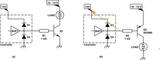
You are trying to create a high-side switch.
simulate this circuit – Schematic created using CircuitLab
Figure 1. (a) NPN open collector switch. (b) A failed attempt to make a PNP version.
Does any one can tell me is that the above configuration is correct and circuit can be use safely?
I can tell you that the above configuration is not correct and can not be used safely.
The low side switch is very simple as shown in Figure 1a. The low-voltage logic just has to feed sufficient current into the NPN transistor to turn it fully on.
There is a temptation to think that we could do the same trick with an PNP transistor as shown in Figure 1b. The problem is that the emitter-base junction is always forward biased. This will apply the 12 V to the chip output and destroy it or, if there are protection diodes on the output, the current will flow through the protection diodes into the micro-controller supply (shown as 5 V in this case). The effect of this current flow is to turn on Q3 and the load can not be switched off.
Figure 2. A high-side switch.