10

I am building an optical pickup using a photodiode connected to a LM741 op-amp. My circuit is similar to this one:

photodiode circuit

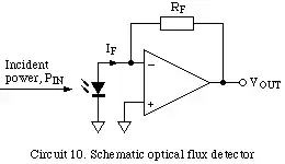
Except that I've added a passive high-pass filter after the output of the op-amp, to eliminate DC (since I am using 0V and +12V as my V- and V+, respectively). I use Rf=500K Ohm (is this way too much?). In addition, I have an LED adjacent to the photodiode that serves as a light source. The LED is powered by 5V and the op-amp is powered by 12V, both from a PC power supply. The photodiode and LED are connected to the circuit using a 2m long guitar cable ("PL").

The circuit works and produces audio signal when I modulate the intensity of the light shining on the photodiode, but my problem is that the signal is very noisy. I can hear/see two types of noise:

  1. Electrical noise similar to a noisy electric guitar pickup. I suspect that it originates in the long cable (or the tip of it, where the photodiode and the LED are conected) collecting ambient electromagnetic noise. This noise is present all the time, even when no light is shining on the photodiode.
  2. Another noise is present only when a signal is generated, i.e only when I modulate the light intensity. I suspect it is a result of amplifying thermal noise, since my gain is very high.

I would like to know what is the best approach, or in other words where to start in my effort to eliminate the noise:

  • Improving the signal to noise ratio at the source, i.e by optimizing the physical conditions (ambient light, precision of the position of the photodiode, etc.).
  • Using a different circuit - I've seen many suggestions on the web and started with the simplest.
  • Using a different op-amp, one that is more suitable as an audio pre-amplifier.
  • Improving the shielding of the pickup itself, to eliminate electromagnetic ambient noise.
  • Using batteries as power source instead of the PC power supply (I am thinking maybe part of the noise is coming form the mains).
  • If none of the above, What would be your suggestion?
abdullah kahraman
  • 5,930
  • 7
  • 59
  • 104
Itamar Katz
  • 225
  • 2
  • 7
  • Can you please provide a link to the datasheet for the Op Amp you are using? – vicatcu Jan 09 '12 at 21:32
  • @vicatcu: He's using a 741. Since that's totally inappropriate, its specs don't matter. – Olin Lathrop Jan 09 '12 at 22:05
  • 1
    Put the thing in a dark room, and then cover it to block even more light. Is the noise still there? I suspect that some (maybe even a majority) of the noise is from "ambient" light. –  Jan 09 '12 at 22:22
  • 2
    33 views at this point and I am the first upvote? I know people want things such as datasheets before they upvote but for some of the trash I see upvoted shouldn't we be promoting someone actually approaching and giving a solid attempt on a problem that they find complex and then asking a question? It does not even have an edit and it already has alot of the details you are needing. – Kortuk Jan 09 '12 at 22:33
  • @vicatcu: I will add a link the the datasheet. David Kessner: I will try it and report, although I think the ambient light only adds a DC to the signal. – Itamar Katz Jan 10 '12 at 07:21

1 Answers1

11

Several things:

  1. A long cable carrying the most sensitive node in the whole system is a bad idea. Carefully shield and then tightly couple the amplifier to the pickup. Then you can send the higher level lower impedance signal over the long cable.

  2. A 741 is a joke in this application. Look for a low noise opamp. There are amplifiers specifically for audio applications where noise matters a lot. Even a general purpose device like a TL07x will be lots better than a 741, both in gain and bandwidth.

  3. Applications that need good lineariry and frequecy response usually use a photodiode in reverse bias configuration. Think of it as a diode that leaks proprtional to light.

  4. Don't try to get all the gain in a single stage, particularly the first one. The first stage should take the little input signal and make is stronger and lower impedance such that it is much less susceptible to noise. The first stage amp can do this better if not run close to its gain-bandwidth product. You don't have to care about offset voltage since audio can be AC coupled between stages. The second stage can then make a nice strong signal that can be sent over 2m wire.

Audio circuit design is mostly about thinking carefully about noise every step of the way. The bandwidth may be low, but the signal to noise ratio needs to be very high.

Olin Lathrop
  • 310,974
  • 36
  • 428
  • 915
  • 2
    He does not have a negative rail on the circuit but is using an inverter without an offset. This probably only gets as little noise from clipping as it does because of the offset generated by the op amp and the relative size of the signal. The high pass also probably helps deal with the clipping. i like your list and thought this might be one more item worth adding, really not worth it as a singular answer. – Kortuk Jan 09 '12 at 22:31
  • @Olin Lathrop: Thanks, your answer is very helpful. Can you please explain what do you mean by "tightly couple the amplifier to the pickup"? Also, what do you mean by "...if not run close to its gain-bandwidth product"? Regarding the DC offset, The only reason I wanted to remove it, is that I wasn't sure if the bass-guitar amp I am feeding the signal to can handle DC. What you recommend as a second stage? – Itamar Katz Jan 10 '12 at 07:32
  • @Kortuk: I am using a scope to make sure my signal is within the dynamic range of the op-amp, i.e no clipping is present in the signal in the light conditions I am using. – Itamar Katz Jan 10 '12 at 07:37
  • @Itamar: By tightly coupling I meant placing the amp physically close to the source. The pickup and amp together can then be more easily shielded, and there won't be long wires to pick up noise. In general, try to leave about 10x headroom between your gain and the gain-bandwidth product. For example, with a 1 MHz opamp, its open loop gain at 20 kHz is 50. That means you should avoid closed loop gains over 5 for that amp if your maximum frequency of interest is 20 kHz. – Olin Lathrop Jan 10 '12 at 13:34
  • @OlinLathrop: Thank you very much. The limit you suggest on the close loop gain is applicable to all amplification stages (1st and 2nd)? Isn't it too small gain for my application? – Itamar Katz Jan 10 '12 at 15:18
  • @Itamar: Like I said, if you are using a opamp in closed loop mode with negative feedback, it's a good idea to have about a voltage gain of 10 headroom. My example of 5x was with a 1 MHz opamp. A 10 MHz opamp can be used to do 50x. I wouldn't want to go over 100x per stage for other reasons. You deal with that limitation by using multiple stages. Remember to AC couple between stages so that the offset voltage does not get amplified along with the signal. – Olin Lathrop Jan 10 '12 at 18:25
  • Olin, How do one does this: "The first stage amp can do this better if not run close to its gain-bandwidth product" Do you mean to say that keep the gain such that its less than x? What is x? I understand that Bandwidth = (GBP/Closed Loop Gain) How does one control the bandwidth and GBP at the same time? How does DC input impacts this? Apologies if this is very basic question but I am trying to learn the "happy" point of any opamp in a simpler way. – Anuj Purohit Mar 10 '15 at 10:23
  • 1
    @Anuj: The gain-bandwidth product of the opamp is what the manufacturer made it to be and you look up in the datasheet. The overall closed loop gain is something you decide. I'm saying that you should set the closed loop gain to be 1/10 or less of the opamp gain-bandwidth divided by the highest frequency of interest. – Olin Lathrop Mar 10 '15 at 13:07