1

I'm building a TTL to fast-NIM converter using an LMH6702 op-amp (datasheet). enter image description here
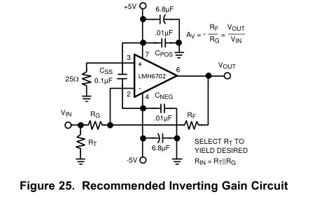
Figure 25 on page 13 shows almost exactly the circuit I'm building, with Rt=50ohm, Rg=3.1k and Rf=237. In that drawing they show that the input resistor to the positive input is 25ohm.

I found here several questions related to that resistors, and they were answered that the resistor needs to be on the same size as the input resistors to the negative input, and in that case I need it to be at about 3.1k.

Is that correct?

Yomach
  • 15
  • 5
  • This is a **current feedback** op-amp, not the more commonplace voltage feedback type. Note above figure 25 says "LMH6702 is optimized for use with a 237-Ω feedback resistor". – MarkU Jul 25 '16 at 06:22
  • Related: http://electronics.stackexchange.com/a/195106/35022 – MarkU Jul 25 '16 at 06:29
  • Ohh, that's a very good comment! thanks! So I'll use 237ohm and 3.91kohm for Rf and Rg respectability. Rt will stay 50ohm as I need the input impedance to be 50ohm. But even in this case, it means that the 25ohm resistor should be 3.91kohm as well or should I keep it 25? Thanks! p.s. Write it as an answer and I'll mark it. – Yomach Jul 25 '16 at 11:16

1 Answers1

0

When the opamp is in service, the voltage at the negative terminal will be at zero volts (a "virtual ground"). The idea of the 25-ohm resistor is to balance the small input bias current that is present on all op amps, so that the voltage generated by this current is equal at both terminals.

This can be accomplished by making the impedance at both terminals equal. You have Rg + Rt to ground (3150 ohm) in parallel with Rf (237). Therefore, the resistance should be 3150 || 237 or 220 ohm.

With your new values 3960 || 237 provides an answer of 223 ohms. Choose the nearest standard value; it does not have to be exact and is only "best practice." In actual practice, the resulting error from choosing a different value will be slight with a good op amp.

John Birckhead
  • 10,524
  • 1
  • 11
  • 27
  • But the CFA has unbalanced input impedance; the noninverting input is lower impedance internally than the noninverting terminal. Usually opamp inputs are base of NPN transistor pair, but in CFA the input circuit is very different. So I'm not sure if the usual rule about input bias current matching applies to a CFA or not. – MarkU Jul 25 '16 at 19:33
  • Good point; the data sheet lists typical -6 uA for one input and -8 for the other, so the ratio of impedance should be changed accordingly. – John Birckhead Jul 25 '16 at 21:09
  • Thanks for the answer; so the resistance should be 8/6 times bigger, or 220*4/3 = 293ohm? – Yomach Jul 26 '16 at 05:04
  • And one more small question, why does Rf (237) goes in parallel with the other two resistors? Rf does not lead to the ground, but to the op-amp output. If it matters, the output of this circuit will go into a 50ohm input on another circuit. – Yomach Jul 26 '16 at 05:06
  • The output impedance of the amplifier is assumed as zero or close to zero, so you don't need to worry about the 50 ohms. You are correct in your calculation for the resistor ratio. – John Birckhead Jul 26 '16 at 20:42