18

Can anyone explain how a transistor can amplify voltage or current? According to me, amplification means - You send in something small, it comes out bigger. Say for example, I want to amplify a sound wave. I whisper to a sound amplifier, & it comes out say, 5 times bigger(depending on the amplification factor)

But when I read about Transistor Amplifying action, all text books say that since a small change in the Base current ΔIb but a corresponding large change in Emitter current ΔIe, there is amplification. But where is amplification? What is being amplified as I've defined it? Is my understanding of the term amplification wrong? And how is current being transferred from a low resistance area to a high resistance area?

I think I've understood how the transistor is constructed & how the currents flow. So can anyone explain the transistor amplification action clearly & relate it to what I understand about amplification.

m.Alin
  • 10,638
  • 19
  • 62
  • 89
Green Noob
  • 1,021
  • 4
  • 11
  • 16

7 Answers7

20

I'll start first with definition of amplification. In the most general way amplification is just a ratio between two values. It does not imply that the output value is greater than the input value (although that's the way it's most commonly used). It is also not important if the current change is big or small.

Now let's move to some common amplification values used:

The most important (and the one your question talks about) is \$ \beta\$. It is defined as \$ \beta= \frac {I_c} {I_b} \$, where \$I_c\$ is the current going into the collector and \$I_b\$ is the current into the base. If we rearrange the formula a bit, we'll get \$I_c=\beta I_b\$ which is the most commonly used formula. Because of that formula, some people say that the transistor "amplifies" the base current.

Now how does that relate to the emitter current? Well we also have the formula \$I_c+I_b+I_e=0\$ When we combine that formula with the second formula, we get \$\beta I_b + I_b + I_e=0\$. From that we can get the emitter current as \$-I_e=\beta I_b + I_b= I_b (\beta + 1)\$ (note that \$ I_e\$ is current going into the emitter, so it's negative).

From that you can see that using the \$ \beta \$ as a handy tool in calculations, we can see the relationship between the base current of the transistor and the emitter current of the transistor. Since in practice the \$ \beta \$ is in the hundreds to thousands range, we can say that the "small" base current is "amplified" into "large" collector current (which in turn makes "large" emitter current). Note that I didn't speak about any deltas until now. That's because the transistor as an element does not require current to change. You can simply connect the base to a constant DC current and the transistor will work fine. If the change in current is required, it's not because of the transistor but because of the rest of the circuit which could be blocking the DC part of the input current.

There is another value also used and it's name is \$ \alpha\$. Here's what it is: \$ \alpha = \frac {I_c} {I_e} \$. When we rearrange that, we can see that \$I_c= \alpha I_e\$. So \$ \alpha\$ is the value by which the emitter current is amplified in order to produce collector current. In this case, the amplification actually gives us a smaller output (although in practice \$ \alpha \$ is close to 1, something like 0.98 or higher), because as we know, the emitter current going out of the transistor is the sum of the base current and collector current which are going into the transistor.

Now I'll talk a bit about how transistor amplifies the voltage and current. The secret is: It doesn't. The voltage or current amplifier does! The amplifier itself is a bit more complex circuit which is exploiting properties of a transistor. It also has input node and output node. The voltage amplification is the ratio of voltage between those nodes \$A_v = \frac {V_{out}}{V_{in}}\$. The current amplification is ratio of currents between those two nodes: \$ A_i=\frac {I_{out}}{I_{in}}\$. We also have power amplification which is the product of current and voltage amplification. Do note that the amplification can change depending on the nodes we chose to be input node and output node!

There are few more interesting values related to transistors which you can find here

So to sum this up: We have transistor which is doing something. In order to safely use transistor, we need to be able to represent what transistor is doing. One of the ways of representing processes happening in the transistor is to use the term "amplification". So using amplification, we can avoid actually understanding what is happening in transistor (if you have any semiconductor physics classes, you'll learn that there) and just have few equations which will be useful for a large number of practical problems.

AndrejaKo
  • 23,261
  • 25
  • 110
  • 186
  • Thanks a lot for answering my earlier questions. But can you tell me why the author has introduced a 5 Kohm resistance in series while explaining voltage 'amplification'?? & where did he get the 20 ohm input resistance? [Link](http://books.google.co.in/books?id=VXIpwBYOjcgC&lpg=PR7&dq=boylestad%20nashelsky&pg=PA138#v=onepage&q=boylestad%20nashelsky&f=false) – Green Noob Jan 06 '12 at 03:14
  • 4
    Does't really answer where the amplification comes from. – rhody May 09 '17 at 22:25
  • 1
    @rhody Back when I was looking at the question, I determined that the main issue is the use of terminology and therefore provided a terminological answer. Since OP already had a referece about transistors, there was no need to go into details explaining what actually happens. – AndrejaKo May 09 '17 at 22:45
  • It is my understanding that amplification is when you increase the signal strength,which is based on the energy carried by the signal and measured in terms of Power(Watts). So an amplifier increases the power. A "voltage" amplifier boosts the signal voltage without lowering the current and this in turn boosts the output power. A "power" amplifier boosts both the AC voltage and the AC current so there is a significant power gain(more than a voltage amplifier). – Mr X Jul 14 '18 at 20:56
  • @Mr X I explicitly disagree with your understanding. Namely, we have the "amplification" as an abstraction tool in general, and then we have practical uses of this tool. I explicitly decided not to try to muddy the water in this answer by referring to the practical uses, because I believe that it's very useful to first understand the abstraction tool on its own. – AndrejaKo Jul 14 '18 at 23:02
  • For example, the "increase the signal strength" part isn't true in all cases when you're designing amplifier chain for say a radio receiver. You might want to include amplifiers with very low or no amplification, but with very low noise figure during the noise figure optimization process. If you look at the amplifiers as something that exclusively takes a small signal and makes it BIG, then noise figure reduction uses can cause confusion. – AndrejaKo Jul 14 '18 at 23:03
  • @AndrejaKo, well you don't need to take my word for it. My definition is echoed here: https://books.google.com/books?id=Yq66DDW4f8IC&pg=PA168&dq=amplifier+power#v=onepage&q=amplifier%20power&f=false – Mr X Jul 16 '18 at 05:23
  • It specifically states that an (electronic)amplifier has a input/output power ratio >1. Which implies that it does indeed increase the power of a signal. Now there are also *operational amplifiers*(Op Amps) that don't necessarily increase the signal power but that's now what the asker is referring to. – Mr X Jul 16 '18 at 05:26
  • @Mr X Well, I disagree with the definition from that book. In my opinion. it's an oversimplification along the "lie to the children" lines. – AndrejaKo Jul 16 '18 at 06:12
8

Transistor does not amplify. Imagine sound waves hitting a microphone: what happens actually is that the sound signal does not pass into the microphone, but the microphone produces a signal corresponding to the sound signal; It is not the actual signal.

Remember that the actual signals in real world cannot be amplified or attenuated. Can you catch a sound or any other real world signal? No. They are as they are, we can only make a system which can work on the effect of the real world signal; sound waves hit on a microphone, light hits on a camera lens etc.

But when it comes to the case of a transistor, you apply an input signal to the base and you obtain a new signal corresponding to the input signal with greater amplitude in the collector. Keep in mind that this happens because a small change in the input side will correspond to a large change in the output side, due to the variation in the resistance. It is only an effect one to one. The output signal is totally a new signal of a grater amplitude, not the actual signal.

m.Alin
  • 10,638
  • 19
  • 62
  • 89
gopal
  • 97
  • 1
  • 2
  • 1
    This doesn't answer the question at all. – rhody May 09 '17 at 22:25
  • Actually the electrical wave and a considerable part of the charge carriers do pass from base to emmiter, hence, we could say the new signal is in part composed by the previous one. But this is quite phylosophical, when for us, signals are voltage levels, measurable, repeatable... – Brethlosze May 14 '18 at 22:14
7

The working principle of a BJT (Bipolar Junction Transistor), which makes it a useful thing, is that it amplifies current. Throw a small current in, get a larger current out. The amplification factor is an important parameter of the transistor, and is called \$h_{FE}\$. A general purpose transistor may have an \$h_{FE}\$ of 100, for instance, sometimes higher. Power transistors have to do it with less, like 20 to 30.
So if I inject a 1 mA current in the base of my general purpose NPN transistor I'll get 100 mA of collector current. That's amplification, right? Current amplification.

How about voltage amplification? Well, let's add a couple of resistors. Resistors are cheap, but if you want to make money you can try to sell them expensive by calling them "voltage-to-current converters" :-).

enter image description here

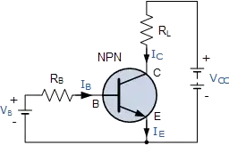
We've added a base resistor, which will cause a base current of

\$ I_B = \dfrac{V_B - 0.7 V}{R_B} \$

And we know that the collector current \$I_C\$ is a factor \$h_{FE}\$ higher, so

\$ I_C = \dfrac{h_{FE} \cdot (V_B - 0.7 V)}{R_B} \$

Resistors are really great things, because next to "voltage-to-current converters" you an also use them as "current-to-voltage converters"! (we can charge even more for them!) Due to Ohm's Law:

\$ V_{RL} = R_L \cdot I_C \$

and since \$V_C = V_{CC} - V_{RL}\$

we get

\$V_C = V_{CC} - R_L \cdot \dfrac{h_{FE} \cdot (V_B - 0.7 V)}{R_B}\$

or

\$V_C = - \dfrac{h_{FE} \cdot R_L}{R_B} \cdot V_B + \left(\dfrac{h_{FE} \cdot R_L}{R_B} \cdot 0.7 V + V_{CC}\right)\$

The term between the brackets is a constant which we're not interested in at the moment. The first term shows that \$V_C\$ is \$V_B\$ multiplied by some factor depending on three constants. Let's use concrete values: 100 for \$h_{FE}\$, 10 kΩ for \$R_B\$ and 1 kΩ for \$R_C\$. Then (again ignoring the constant factor)

\$V_C = - \dfrac{h_{FE} \cdot R_L}{R_B} \cdot V_B = - \dfrac{100 \cdot 1k\Omega}{10 k\Omega} \cdot V_B = - 10 \cdot V_B \$

So the output voltage is 10 times the input voltage plus a constant bias. Looks like we can use the transistor for voltage amplification as well.

stevenvh
  • 145,145
  • 21
  • 455
  • 667
  • 2
    In the strict physics sense, transistors do not amplify current, since even the bipolar transistor is controlled using the base emitter voltage, but I agree it's a convenient shorthand. http://amasci.com/amateur/transis.html – Mister Mystère Mar 19 '15 at 17:38
  • @MisterMystère: a bipolar transistor in common emitter is controlled by base current, not voltage. It's the base current that causes an X times larger collector current. You're wrong. – Joris Groosman Mar 20 '15 at 15:32
  • @JorisGroosman Ever heard of the textbook "Art of Electronics?" They teach bipolar transistors with voltage-input design philosophy, not current input. Author Win Hill specifically points out all the flaws in the hfe-based, current-input viewpoint, and shows how they're solved by seeing BJTs as voltage driven; ruled by the Ebers-Moll equation. He points out that current-input doesn't apply to diff amp, current mirror or cascode. Check out one of his forum responses about BJT voltage input versus current input: http://cr4.globalspec.com/comment/720374/Re-Voltage-vs-Current – wbeaty Mar 21 '15 at 10:57
  • 1
    @wbeaty: Yes, I know AoE. Odd thing: since the 1950s engineers have calculated collector current as a function of base current is a gazillion of **practical** applications, and they all **work**! Current as a function of base voltage probably doesn't go beyond the blackboard. – Joris Groosman Mar 23 '15 at 17:36
  • No,you don't know AOE, since they show why hfe DOESN'T work for analog design. Amps based in hfe will fail if temp drifts a couple of degrees. The authors push the voltage-based BJT design philosophy. As Win Hill points out, hfe doesn't explain voltage-input stages such as emitter-followers or diff amps. Op amps and their voltage inputs are hardly a blackboard-only concept. They worK, and are immune to vast changes in the hfe of the transistors involved. Yes, hfe is a useful concept, but without voltage-based signals and Ebers-Moll, a large part of modern analog design would fail. – wbeaty Apr 03 '15 at 04:52
  • @wbeaty: Like I said, look at existing designs. **No** engineer will occupy himself with Ebers-Moll for a practical application, no matter how theoretically correct. Ever heard about the word "pragmatic"? – Joris Groosman Apr 03 '15 at 14:31
  • @JorisGroosman You mean like op amps? As AOE points out, op amps (long-tailed pair) are based on Ebers-Moll. So are the current sources used everywhere in silicon electronics. So are emitter-follower buffers. In other words, most existing designs are voltage-based, and do not rely on hfe. If you – wbeaty Apr 12 '15 at 04:35
  • Oops, timedout. Of course we don't have to laboriously solve Ebers-Moll, it's built right into our spice models, and the operating principle of op-amp front ends. (Try setting Vbe to a constant, watch your designs all fail. Now try using Ebers-Moll model but setting hfe to infinity, and they'll work fine.) Really, just go read AOE transistor chapter. Anyone who does so learns that it's all about the practical designs used everywhere, all of which are based on voltage, and they ignore hfe. They have to, since hfe-based design doesn't work, it's temperature sensitive. – wbeaty Apr 12 '15 at 05:15
  • There are many transistor-circuits which CANNNOT be explained using the (false, but sometimes working) current-control approach (current mirror, opamp-based log amplifier, tanh-curve for diff. amplifier, Re-feedback with input resistor increase, even the Early-effect,...). – LvW Feb 06 '16 at 10:17
  • What a transistor amplifier does is use transistor action to add energy to an AC signal by storing energy it receives from a DC power source. None of the answers here seem to explain transistor action from the standpoint of physics. – Mr X Jul 14 '18 at 20:58
5

The signal is being amplified. Depending on the design of the transistor amplifier the actual base current may or may not be part of the output current. Don't get hung up on a definition of amplification that requires every input electron to get larger and then pass to the output...

Ben Jackson
  • 789
  • 3
  • 13
  • Please explain? – Green Noob Jan 05 '12 at 07:59
  • @GreenNoob - most transistor amplifiers have *bias currents* that ensure the circuit is operating linearly. With just the bias currents present, it will be true that emitter current is greater than base current, but this isn't very interesting since these currents are just constants. The books speak about *changes in current* b/c the signals we ordinarily think of amplifying are imposed as fluctuations on top of the bias currents. – JustJeff Jan 06 '12 at 03:27
3

Amplifiy sound, and you're amplifying the energy-flow: the input watts of sound become larger output watts.

Note that an electrical transformer doesn't amplify. It can step up voltage, but it cant increase the watts.

Transistors (and any sort of valve or switch) can amplify. They do it by using a tiny wattage to control a power supply which can output a huge wattage. The large output comes from the power supply, while the input signal is valving the transistpr on and off.

If you have a giant hydraulic press, you can crush cars by touching a valve switch with your little finger. The valve amplified your finger motion to mash Chevys. But actually it was the hundreds-HP haudraulic supply which provided the increased wattage. With NPNs, same idea. Transistors are valves for flowing charge instead of flowing haudraulic fluid.

wbeaty
  • 10,761
  • 23
  • 39
  • Nice explanation... To move it to the electrical domain, we can simply say the transistor is an "electrically-controlled resistor" inserted in series ("rheostat") or in parallel ("shunt") to the load. Thus it forms a voltage or current divider. To be more precise, we can only add that this "resistor" is non-linear, and it is controlled both by the side of the input source and the load. And also, the transistor is a passive, not active device (regarding the power). – Circuit fantasist Jan 28 '15 at 08:49
  • From this "energy viewpoint", the transistor does not amplify; contrary, it attenuates the power of the source... it does not produce energy; it consumes energy. – Circuit fantasist Jan 28 '15 at 09:00
  • reading all the answers of yours really helps me a lot, especially thanks to @wbeaty, your explaination is realllly nice! –  Mar 19 '15 at 17:29
  • Your car crush analogy is soooo much easier to understand than a water valve. Thanks! – dval Jun 17 '16 at 12:52
0

What is my understanding is that for a transistor to amplify you need to bias it properly. Forward biasing of BE junction makes it a conducting diode so input resistance is less. Reverse biasing CE junction makes it non conducting diode so output resistance is high. And if Ic is almost equal to Ie then the current causes a low voltage drop at input and large one at output. This is why its called an Amplifier.

Aditya
  • 1
0

With a transistor, you can achieve this: Give a small signal(ac) at input, and get a larger valued(higher amplitude) signal at output. But this is not all. You have to give DC supply at collector and base; emitter if required. This is called biasing the dc point. The rms power you get at the output will be less than the dc power you have supplied.

If you want to do analysis, there are two steps involved for any circuit.

  1. DC analysis: don't consider any ac signal. Find out the values of all diode currents based on dc voltage at various nodes(Collector, base , emitter). This is done by using KVL along various loops.

  2. AC model: Image has been taken from the book "Electronic Devices and Circuit Theory
    This makes very clear: what we draw as a circuit v/s what elements are actually present inside. Going further, the diode has forward resistance. So the actual model will be like this:

From DC analysis, you must have found the value of Ie. According to diode theory, Re = (26mV/Ie). Our aim is to find Vout/Vin.
1. Vout will depend on Ic.
2. Ic will depend on Ib.
3. Ib will depend on Vin and Re.
4. Re we have found from DC analysis.

enter image description here In AC analysis, we make all the DC supply to 0V. By looking at this, you can make out that the output signal will be an amplified one, right?

Note: This was just to give you an intuitive idea that amplification does take place. But whether you will get amplification or not depends on whether the transistor is in linear(amplifier), saturation or cut off(switch). Again, what will be amplified(current or voltage) depends on type of configuration. So that all comprises of 3-4 chapters of any standard book on analog theory.

explorer
  • 250
  • 3
  • 11