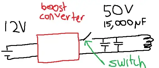
Your drawing does not match your description. You say the boost converter charge up the capacitors, then you activate your switch. If the switch is open and located as you've drawn, then there is no way the boost converter could charge anything.
Also, as you've drawn your circuit, the solenoid would always be connected to the capacitors, so I don't see how the capacitors would ever become charged, you'd just be shorting the boost converter through your solenoid with the caps in parallel.
Please draw an accurate picture if you're going to draw one at all. As it stands now, it would actually have been better without a picture, as the one you've drawn is wrong and just confuses things.
I'm assuming you meant to draw the switch between the capacitors and the solenoid, not between the capacitors+solenoid (permanently tied to each other) and the boost converter. In other words, the switch causes the capacitors to dump their stored energy into the solenoid when closed.
It's no surprise your switch destroyed itself, higher voltages translate into much higher currents, especially with that much capacitance. You can ablate pits in screwdrivers with a capacitor charged with 50V. The problem is that mechanical switches begin conducting at the earliest possible time, which is going to be before it has established good contact. The initial connection will not be nearly as low resistance as you'd expect, and with lots of current, it will get quite hot, and you will either vaporize some of the metal contact area, or if the switch is very underrated for the application (like in your case) it will fail in a variety of spectacular ways.
You're doing a one-shot, right? As in, you flip the switch, you dump the energy in the capacitors into your solenoid, and that's it? That was the 'one-shot'. Now you have to start over and recharge before you go again. If that is the case, you should use the component that is designed specifically for this. An SCR. They are built like tanks. The inductance of the solenoid likely limits the current to as little as 50A, but lets assume you have a really badass setup, and the total resistance of the capacitors AND the solenoid is about 3mΩ because you're using 1" square solid copper bars as wiring, and lets say this is a low turn solenoid, and only has 2mH of inductance (unusually low for a solenoid). In those unlikely circumstances, you won't even hit 150A peak. 100A is far more likely.
So, just use this.
It's $1.39, it can handle 160A 60Hz half cycle, which is more than even the most pessimistically (optimistically? Depends if this is a solenoid or a coil gun) high currents you might see and on the time scales they will happen. Those time scales being less than 60Hz half cycle equivalent, thanks to all that inductance. It is solid state so will not slowly be destroyed every time it makes contact like a mechanical switch or relay, and it is specifically built to withstand the stresses you will be subjecting it to. Over and over.
They are incredibly easy to use too - you just squirt a little current into the gate pin, and it will trigger it. The gate is cathode referenced, so if you used it high side (on the positive rail of the capacitors) and had a common ground with an arduino, then the cathode would be effectively ground referenced through the solenoid. You need a little kick to trigger it, the datasheet says 9-30mA. An arduino can do 40mA on one I/O pin, so just put a 150Ω resistor between it and the gate, and you're good to go. Take the IO pin high and the SCR will trigger. Once the current through the solenoid has fallen below the holding current, the SCR will turn off and resume blocking any current from flowing through it. At least, until you trigger the gate again.
In your comments, you mention "SSRs", which I assume is referring to SCRs, are expensive. Expense is relative, but you will not find a cheaper solution than an SCR, so hopefully $1.39 is not too expensive. If it is, there is always taping two wires to a piece of wood and grabbing a shovel. Just close your eyes first. (I speak from experience hehe).
Almost forgot: Put a few beefy diodes the 'wrong way' across your solenoid coil, so they have their cathode going to the positive terminal of the capacitors, and anode to ground. Or your Arduino will explode.
