6

I'm trying to design a circuit that will let me drive an LED or Diode laser with a RF signal up to ~20 MHz or so. Since the optical device will need to be biased with a DC current, a bias -t is a natural choice. I was planning on using a GALI-84+ amplifier from Minicircuits to amplify my RF signal and then pass it into a bias-T circuit, however when I was looking at the schematic for the eval board for the GALI-84+, I noticed that the output of the amplifier is biased using an inductor and a DC supply, before it is AC coupled using a capacitor to the output.

I contact Minicircuits asking if I could remove the coupling capacitor and use this circuit to both bias the diode and amplify my signal at once, but they said:

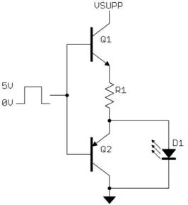
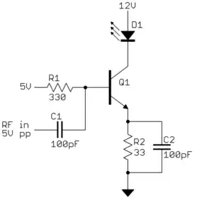
The GALI-84+ is an RF amplifier designed to drive 50 Ohm loads. To drive an LED, you will need to configure the amplifier conventionally, detect the RF output signal using a simple diode detector and use it to turn on a transistor with the LED in the collector.

They described the diode detector as, "a series small signal Shottky diode feeding a 1K resistor to ground", and then connecting the Shottky to the base of a transistor.

So, now I'm confused:

1) Why use a diode detector? 2) Will I harm something if I use the GALI to drive a non-50ohm load directly?

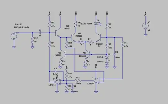
Update Is there any reason I can't use this configuration to drive my LED? Since the amplifier seems to be a Darlington pair, wouldn't this be appropriate for driving a variable current? The non-handdrawn portion is the Gali-84+ schematic from the datasheet.

enter image description here

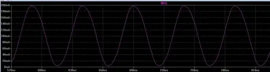
Update A few details on the specifics. I need to dive a diode laser, with up to 200 mA of current. The laser turns on at about 4v, with 40 mA of current, and will be driving about 200 mA by 5.5v. I need to bias the laser on (above the cut-on voltage) and drive it with an AC signal. So, bias at 4.75v and driving with a +/- 100 mA current, or +/- 0.5v. The diode is extracted from BlueRay DVD players, and as such, I don't have detailed specifics on its behavior.

Thanks.

gallamine
  • 1,112
  • 3
  • 11
  • 19
  • 3
    They think you want to use their 6 GHz amplifier to amplify 6 GHz signals. They know that you can't switch an LED at 6 GHz. They think you just want the LED for a "signal present" indicator. – The Photon Jan 04 '12 at 00:24
  • You could probably do what you want with a much less fancy part. But if you really want to use this part, they only cost $2 each. I don't see any reason not to just try it. – The Photon Jan 04 '12 at 02:57
  • RE: Bounty. Whether the whole circuit works will depend on the capacitance of the LED and other factors you haven't revealed. In the time since you've asked the question, you could have built and tested the circuit. It's not an expensive part. Why not just test it? – The Photon Jan 06 '12 at 17:58
  • I added some details. I haven't tested it, because I have a limited supply of lasers and I can't afford to blow them up. Wanted to get some informed opinions first. – gallamine Jan 09 '12 at 13:26
  • A datasheet for the laser (or LED? which one is it?) that you are using would be very helpful if you want more helpful answers. – The Photon Jan 09 '12 at 17:33

4 Answers4

7

I'm not following what exactly this Minicircuits thing is, but it sounds like they thought you want to turn on a LED when RF is present, hence the detector. It seems you actually want to drive the LED with 20 MHz.

At that speed, it's a good idea to actively turn off the LED, not just on. I haven't tried this, but this double emitter follower might do what you need:

When the digital output is at 5V, there should be around 4.3V on the emitter of Q1, which should be enough to turn on the LED thru R1. If D1 needs about 2V, for example, then R1 of 47Ω allows about 50mA thru the LED. Of course you need to adjust this for your particular LED. Note that you can drive it at twice its rated average current since you'll be doing it for half the time.

When the digital output goes low, the emitter of Q2 will go to about 700mV. That's a lot less than what it takes to turn on the LED, and will actively remove some charge to turn off the LED quicker. A ordinary CMOS 5V logic gate should be able to drive this circuit. I don't know why you think you need some sort of amplifier in there.

Added:

The circuit you show will work to drive the LED since it can drive 0 to some maximum current thru the LED as a function of the control signal. However, the big question is how well it will work at 20 MHz. At that frequency you have to think about semiconductors being actively turned off, not just on. You have nothing to actively turn off the LED (that's what Q2 is for in my circuit). You do have resistors to ground on both transistor bases, but you have to think about the values carefully to make sure the transistors turn off fast enough.

You haven't said what the maximum LED current needs to be, so I can't tell whether you really need the gain of two transistors to make a controlled current sink. Unless the current is really high (100s or mA or more), the gain of a single transistor is likely enough and it will be easier to drive a single transistor effectively at 20 MHz.

Added 2:

You now say you want to run the diode in linear mode with a bias of 125mA and a signal level of +-75mA from that. Here is something that might work. I say "might" because there are too many unknowns, especially at 20 MHz. You will have to test and adjust according to what you find:

Q1 acts like a voltage-controlled current sink. R2 is adjusted to get the right bias current with no RF signal in. With 5Vpp AC added to the 5V bias on the base of Q1, the current should vary about over the range you want.

C2 is only for a bit better speed. I took a rough stab at a plausible value, but you'll have to experiment to see what works best in your setup. It will depend on how slow the transistor really is. Note that since this is running the LED in linear mode, there is nothing actively removing charges from the junction when lowering the current. Actual light output will therefore probably lag decreasing current a bit. How much depends on things we don't know at this point. C2 will make the current lead the input voltage a bit in a attempt to compensate for the slowness of the diode and the transistor.

Olin Lathrop
  • 310,974
  • 36
  • 428
  • 915
  • 1
    Thanks for the detailed reply Olin. I'm specifically looking to bias my LED/laser and then modulate it with a RF signal (subcarrier intensity modulation). I can't tell if your circuit will work well with linear small-signal modulation. – gallamine Jan 04 '12 at 02:11
  • @gallamine: What I showed is intended for driving the LED on and off. You want to drive it with a sine wave or something? Why? – Olin Lathrop Jan 04 '12 at 16:12
  • 1
    I'm using it for freespace optical communication. I need to transmit a RF signal using the optical intensity. – gallamine Jan 04 '12 at 18:34
  • You're not going to be able to drive a laser diode with a sine wave. Also, that MMIC amplifier is designed to run class-A, with the transistors on at all times. You could try biasing it into class C but the Darlington pair might not even be able to switch on and off at 20 MHz... and as Olin says, you still need to actively pull the output down somehow. – John Miles Jan 05 '12 at 07:32
  • @gallamine: "freespace optical communication" doesn't explain why you need to drive the LED other than on/off. – Olin Lathrop Jan 05 '12 at 14:01
  • Olin, I'm doing subcarrier intensity modulation using a RF subcarrier on the lasers intensity output. The biased intensity of the light source is proportional to the RF input voltage. – gallamine Jan 05 '12 at 17:55
  • @JohnMiles actually I drive these LEDs and lasers with RF signals all the time. You just need to bias them first. I'm trying to take the individual components on the bench and make a custom PCB. I use the GAL-84+ coupled with a RF bias-t, but I'm trying to simplify things and remove the 2nd bias-T. – gallamine Jan 05 '12 at 17:56
  • Transistors in this scheme will go into saturation, and their turnoff times would be up to 300ns => very far from 20Mhz. – BarsMonster Jan 09 '12 at 03:35
  • @OlinLathrop I need to dive my diode laser with a bias of 125 mA and a maximum signal of +/- 75 mA. – gallamine Jan 09 '12 at 15:04
  • @OlinLathrop is there a particular Q1 that'd you'd recommend? Thanks! – gallamine Jan 10 '12 at 23:43
  • @gallamine: Asking for reasonable gain at 20 MHz is enough so that I'd look at datasheets and not just pick a well known part. That requirement shouldn't that hard to meet, but since I haven't specifically looked around for that, I don't have a part to recommend. – Olin Lathrop Jan 11 '12 at 12:51
6

Here's a quick circuit I came up with in LTSpice that should drive an LED or laser diode to 20 MHz, assuming the device is capable of such:

enter image description here

Here's the current into the LED at 20 MHz, for 1 volt p2p input:

LEDDriverOutput

I haven't tested this circuit in real life - don't blame me if it blows up! The particular components should not really critical except for keeping power dissipation in mind; the 2N2222s in the differential pair (Q1 and Q2) are plenty fast for a sine wave at 20 MHz, but will be run near the limits with respect to power dissipation and should probably be connected to a small heatsink. Q6 will dissipate about a watt and should be some kind of small power transistor in a TO-220 package to handle the dissipation. I imagine circuit layout will need to be done carefully for best results.

The 2 opamp sections are a bias servo, and can be any dual single supply opamp, like an LM358. This is kind of a quick hack, is probably not optimized, and it doesn't have any nice features; the output current will be distorted because there is no global feedback from the diode, there's no protection circuitry for the diode, etc.

Designing a modulator that included all the bells and whistles and also works at 20 MHz will most likely be a non-trivial task!

MattyZ
  • 2,926
  • 1
  • 22
  • 23
  • I feel so stupid when I see answers like this – abdullah kahraman Jan 10 '12 at 12:19
  • 1
    @abdullahkahraman It's not too complicated if you take away the op amps and stuff. It's basically just a differential amplifier, Q1 and Q2, with a driver transistor Q3. Q5 and Q6 are current sources used to set the bias of the transistors. The op amps are a bias servo that compares and low-pass filters the voltages on the two differential transistor bases, and makes sure that at the quiescent point there is always a nearly equal current flowing through both of them. – MattyZ Jan 10 '12 at 13:39
  • 1
    @Bitrex, does the circuit still work if the 2n2222's are not well matched? I was always taught that diff amps like this (implemented with discretes) will work in simulation, but not in real life, due to mismatch issues. But I've never tried it in real life, and the part uniformity might be better than I expect. – The Photon Jan 10 '12 at 16:58
  • 1
    @ThePhoton Adding emitter degeneration resistors R1 and R2 help make the differential pair insensitive to device parameters. If you just stuck two discrete 2N2222 transistors together at the emitters and put the same voltage at their bases in a differential pair, and their characteristics weren't matched, they might not share current very well. Adding negative feedback (degeneration) improves things a great deal; in the simulation you can actually use totally different types of transistors (like a 2N2222 and 2N3904) and the current is only off by a few mA. – MattyZ Jan 10 '12 at 19:44
  • 1
    @ThePhoton Degeneration also gives lower distortion. The tradeoff for this of course is lower gain, but unmatched discrete differential pairs with emitter degeneration are used all the time. In some circuits (like exponential and log converters) adding degeneration is not an option, so you have to match the device characteristics, or use an IC that has matched pairs onboard, like a CA3046: http://www.intersil.com/data/fn/fn341.pdf – MattyZ Jan 10 '12 at 19:48
1

Please take a look at my question BJT push-pull modification on how to drive BJT fast. You darlington pair would be very slow, shutting off would be up to 100ns-300ns.

The second point is that you should not turn off your LED completely, because it would slow down next turn-on. You need to always feed very small current to LED, like 0.1-1mA, so that is glow very slightly.

If you get best push-pull circuit from my question, and feed signal to led through a fast diode (1N4148 should do the job with it's 2-4ns times) & current limiting resistor, the only thing you would need to add is high-value (some 10k-100k) resistor from the VCC and then a diode to your LED. The idea is that when led is turned off by BJT's if will get small current from VCC through high-value resistor.

BarsMonster
  • 3,267
  • 4
  • 45
  • 79
  • The diode laser needs to be biased at +40 mA to achieve turn-on. I like your answer, but it looks fairly complex, and I'm on a short timeframe to get things working "well enough". Do you have any insight on specifically using the GALI-84+ to drive a diode laser or LED? Thanks! – gallamine Jan 09 '12 at 13:32
0

The main issue I see is that with what you propose the LED bias will be equal to the RF amplifier bias. If the ideal bias for the amp is different from the ideal bias for the LED, you'll have to make a compromise, or experiment to find out what works best.

Also, the amplifier is designed to provide the specified gain when it has a 50 Ohm RF load, but has whatever is the specified DC load providing bias. You will not be operating it with the designed RF load, so the gain achieved will not be what the datasheet says. If the current limiting resistor is greater than 50 Ohms you will probably get more gain than expected, and less bandwidth.

Nonetheless, it's a high-gain amplifier designed for 6 GHz and you're using it at 20 MHz...there's a good possibility it will work adequately.

Edit

You mention you are concerned about damaging your laser, which you have in limited supply. Nothing in this circuit is likely to damage your laser. Things that are likely to damage your laser are

  • Overvoltage, including power supply glitches and turn-on transients
  • Over-current
  • ESD
  • Over-temperature

How to deal with these would be a separate question.

In one place you say you want to bias the LED/laser at 100 mA, in another you say 125 mA, and in another you say 200 mA. Since the amp has an abs max bias current of 160 mA, you will not be able to do 200 mA with this scheme. If you want 100 mA, you are in very good shape, that is exactly the recommended bias current for the amplifier. If you want 125 mA you are probably okay, but you are not operating the amplifier in its recommended operating conditions, so performance or reliability may suffer, and you would want to pay special attention to heat-sinking the amplifier.

The Photon
  • 126,425
  • 3
  • 159
  • 304
  • I just saw the recommended operating current for the amp is 100 mA. That might be somewhat high for a high-speed LED...If you want to know how the amp behaves with 50 or 25 mA bias, MCL won't tell you -- you'll have to experiment for yourself. – The Photon Jan 06 '12 at 18:11
  • Diode lasers work at this current. Also the high power LEDs, like the Cree XR7090's work at 700 mA and have an operating bandwidth of 10 Mhz (full on, full off) and a Gain-bandwidth product out to 80 MHz. – gallamine Jan 09 '12 at 13:28
  • Is that the LED you are using? If you are using a different LED, 100 mA might be too much; or, it might not. – The Photon Jan 09 '12 at 17:20
  • Incidentally, nowhere in the Cree XR7090 datasheet (http://www.cree.com/products/pdf/XLamp7090XR.pdf) do I see a claim of 10 MHz switching bandwidth, or even a capacitance spec that would suggest 10 MHz is possible. It may be possible to switch this device at that speed, maybe with a circuit like Olin's first proposal; but it would probably take some seriously beefy driver transistors to do it, or maybe some kind of resonant circuit. – The Photon Jan 09 '12 at 17:30
  • Cree doesn't design them for communication, just illumination. They have, however been successfully used for 10 Mbps baseband communication, 80 Mbps with equalization, and I have tested their RF response up to 15 MHz. Can provide references if you'd like. I'm more concerned about driving the laser diode. – gallamine Jan 09 '12 at 22:42