5

I want to design a variable voltage regulator that will get from it`s maximum output (lets say 10V) down to 0V (or very close) considering the input as regulated 12V (from a PC power supply).

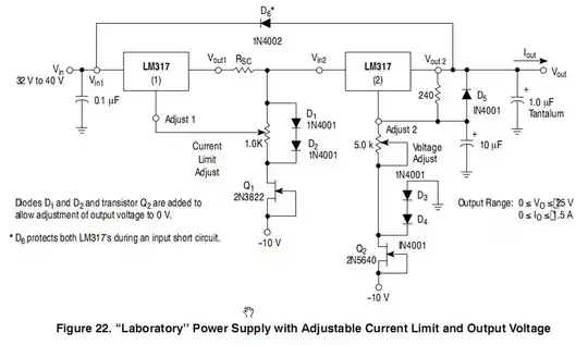
All the designs that I found use the 317 IC and can not go under 1.25V and I am pretty sure that there must be a way to do so.

I could not find any tutorials that explain in an easy way the way that the 317 behaves (beside the classical configuration) so any additional explanation is welcomed.

Transistor
  • 168,990
  • 12
  • 186
  • 385
Virgil Litan
  • 174
  • 1
  • 1
  • 10
  • 1
    Have you tried the datasheet yet? – Ignacio Vazquez-Abrams Jul 04 '16 at 22:34
  • 3
    Is the LM317 the only adjustable regulator you can get your paws on? Because there are more modern regulators that can regulate down to 0V without as much work...do you have a minimum load for this supply? – ThreePhaseEel Jul 04 '16 at 23:41
  • @Virgil Litan, a useful explanation and demonstration of an LM317 implementation that can output 0V: https://youtu.be/CIGjActDeoM – venzen Jan 14 '17 at 05:03

4 Answers4

8

To get the LM317 down to zero volts you need to bring the control pin down to -1.25 V.

enter image description here

Figure 1. This dual LM317 circuit consists of a current limiter based around LM317(1) and a voltage regulator based around LM317(2). The voltage regulator section is relevant to this post as it is adjustable down to zero volts. Source: ON-Semi datasheet.

  • The control pin of LM317(2) is pulled low by Q2 which is wired as a simple constant current sink pulling several milliamps from the adjust pin.
  • D3 and D4 clamp the top of Q2 at two diode drops (2 x 0.7 V) below zero (-1.4 V).
  • The 240 \$\Omega\$ resistor and 5k pot can then adjust from zero up to the supply limit.

The problem with this circuit is that you need to generate a negative supply capable of sinking the few milliamps. My answer to Smartest way to use current limit using LM317? (where I explained the current limiting section) may help in this regard.

schematic

simulate this circuit – Schematic created using CircuitLab

Figure 2. If a centre-tapped transformer is used the negative rail can be generated quite easily. In this example a half-wave rectified signal is smoothed by C2 which doesn't have to be very large.

Transistor
  • 168,990
  • 12
  • 186
  • 385
  • 3
    You know this. Others mightn't: The use of D3 + D4 as a 'voltage reference' in the ONSemi LM317 app note fig22 circuit is a terrible choice by the ONSemi 'designer'. The two diodes form an extremely poor reference (even when current driven as they are by the low-accuracy (irrelevant here) JFET current sink. Far better would be to use a [**TL431**](http://www.nxp.com/documents/data_sheet/TL431_FAM.pdf) 2.5V shunt regulator or [**TLV431**](http://www.diodes.com/_files/datasheets/TLV431.pdf) 1.24V version (the latter having a 0.2% accuracy option). ... – Russell McMahon Jul 06 '16 at 00:04
  • 1
    ... The 1.24V can be used directly as the -1.25V reference or adjusted to 1.25V if desired using two (precision) resistors. | LM317 reference accuracy varies but can be as poor around +/- 5% eg [this example](http://www.onsemi.com/pub_link/Collateral/LM317M-D.PDF) – Russell McMahon Jul 06 '16 at 00:05
  • @RussellMcMahon how about sending feedback via biased OPAmp? still need negative power source, but I think precision can be improved since voltage reference is effectively excluded from feedback circuit. – Maple Feb 29 '20 at 20:46
  • @Maple Yes - an op amp could be used, although using eg a TL431 or TLV431 would probably be accurate enough for its error contribution to be "lost in the noise" of the other sources of error. – Russell McMahon Feb 29 '20 at 21:07
7

A somewhat nasty solution is to place two silicon diodes of suitable current rating in series with the LM317 output (after the voltage-setting resistor divider). This would reduce the output voltage by about 1.4 volts. This will degrade the voltage regulation slightly, as the diode voltage drop will vary with load current.

A better solution is to provide a -1.25 volt (or so) low current supply to the bottom of the voltage setting resistors, rather than connecting that point to ground.

Peter Bennett
  • 57,014
  • 1
  • 48
  • 127
3

A regulator is an amplifier which stabilizes the output at a target voltage. The LM317 does this by comparing the output to a 1.25V reference, and while you can get higher voltages than 1.25 (by voltage dividing the output) you cannot get lower (voltage dividers top out at 1:1).

Instead of an LM317, you can use an operational amplifier that senses near ground, and for a 20V range, divide output by a fixed ratio (20:2.5) and amplify difference of that divided output to a second divider on a 2.5V reference voltage (TL431 being a suitable reference source).

When the reference divider is at 1, output stabilizes at 20V; when it is at 0, the output stabilizes at 0V.

See figure 13 here: http://www.ti.com/lit/an/snoa589c/snoa589c.pdf

Whit3rd
  • 7,177
  • 22
  • 27
  • "_ The LM317 does this by comparing the output to a 1.25V reference, and while you can get higher voltages than 1.25 (by voltage dividing the output) you cannot get lower ..._" Yes you can get lower than 1.25 V. It's explained in the datasheet referenced in my answer. – Transistor Jul 05 '16 at 18:17
  • The answer is correct in principle but incomplete. The OA needs either to be a "high power" one or, more usually, to drive a power stage which is perhaps adumbrated but not made clear. | Transistors point can be addressed by adding eg "... without also needing a negative supply voltage". | The LM317 has current limit, thermal shutdown and is reasonably robust when mistreated. Use of an opamp + LM317 in some manner has advantages. – Russell McMahon Jul 06 '16 at 00:13
  • The use of an LM317 has a single disadvantage, as well: it works according to its specs only when it delivers 5 mA or more from the 'output' pin. Unless there's negative voltage, that output pin will misbehave at low V (the 'adjust' output resistor draws the necessary current in 1.25V-and-higher connection). – Whit3rd Jul 07 '16 at 04:57
0

if there is sufficient loading, try one LED to drop a fairly constant voltage. You an always bury it where it can't be seen.