When connecting a 10S LiPo (42V) to my ADC via a voltage divider, I began wondering how to calculate the output impedance of the divider.

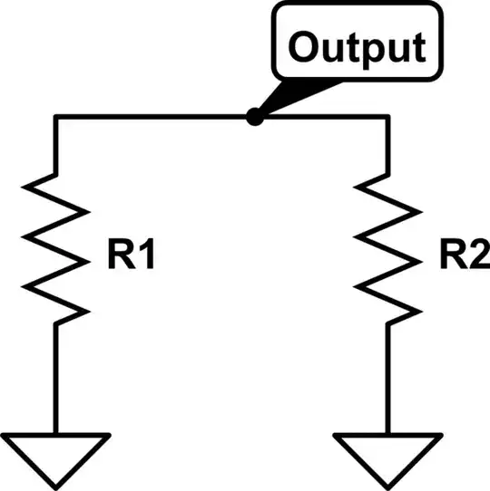
simulate this circuit – Schematic created using CircuitLab
For example, what is the output impedance of the above circuit?
(The ADC's specs recommend a signal impedance of 10kOhm or less, which I simply translated to 0.5mA @ Vcc=5V (worst case) and figured I'd be fine as long as the signal can source/sink more than 0.5mA. But that's not really 'calculating' the impedance...)