6

I would like to design a bandpass filter to isolate the musical note A2 ( 110Hz ) from its neighboring notes at a precision of a half-step. This means that G2# = 103.83Hz and A2# = 116.54Hz should be in the stop band.

In the ideal case, 110Hz would be at 0 gain. G2# and A2# would be silent (infinite negative gain?), and there would be a smooth roll-off from the A2 to each neighboring note.

How can I select my window type, determine how many coefficients are necessary, and calculate those coefficients?

I took a few EE courses back in college, but I am far from an electrical engineer, so please ask for clarification where it is necessary.

References:

user664939
  • 163
  • 1
  • 5

5 Answers5

9

As I understand it, you want to detect the amplitude of 110 Hz component with a bandwidth of less than the 12th root of 2 on either side. The adjacent notes that should not be detected are 103.8 Hz and 116.5 Hz, which are about 6% off from the center frequency.

First, that is a very tight filter. This is not going to happen with analog electronics, at least not in the baseband.

You can do this digitally by sampling the composite input signal and multiplying it by the sin and cos of 110 Hz. Low pass filter each of these products so that 6 Hz is attenuated to the level you want adjacent notes attenuated. Then square each of the results and sum them. That single number will be the square of the recent amplitude of any 110 Hz component in the input signal. Keep in mind that since this filter has very narrow bandwidth, it will respond slowly. It will take a few 100 ms to stabalize from a step in the incoming 110 Hz amplitude.

If you just want to detect that the 100 Hz component is above some threshold, then you can use the squared amplitude value directly. If you need the real amplitude, then you'll have to take the square root of the result.

I have done something similar to detect individual DTMF frequencies in a DTMF signal. The frequencies, bandwidth, and therefore the time constants are different, but the algorithm is identical. Here is a result showing the amplitude squared value I described above for three successive DTMF frequencies with the algorithm set up to detect the middle one:

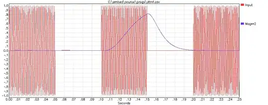
Here is the code snippet that ran over each input sample to produce the squared magnitude (MAGSQ) and the real magnitude (MAG):

  for sampn := 0 to nsamp do begin     {once for each input sample}
    t := sampn * sampdt;               {make time of this sample}
    samp := getsamp (t);               {get input sample}
    r := t * freq;                     {make reference frequency phase}
    ii := trunc(r);
    r := r - ii;
    r := r * pi2;
    prods := samp * sin(r);            {mix by ref frequency sine and cosine}
    prodc := samp * cos(r);
    filter (filts, prods);             {low pass filter mixer results}
    filter (filtc, prodc);
    magsq := sqr(filts.val) + sqr(filtc.val); {compute square of magnitude}
    magsq := magsq * 4.0;              {normalize so input 1.0 results in 1.0}
    mag := sqrt(magsq);                {compute linear magnitude}

The FILTER subroutine performs a two pole low pass filter the usual way. Each pole follows the standard algorithm:

FILT <-- FILT + FF(NEW - FILT)

In this case FF is 1/128. Since it is a integer power of two (-7 in this case), it could be performed in a microcontroller by a right shift of 7 bits.

Olin Lathrop
  • 310,974
  • 36
  • 428
  • 915
  • I think the LM567 tone decoder IC uses basically this technique. http://www.ti.com/lit/ds/symlink/lm567.pdf – MattyZ Jan 01 '12 at 03:14
2

As Olin noted - bandwidth is very narrow for analogue. Very.

A PLL may well rise to the challenge.

Sounds very much a job for a lock-in amplifier. Which is arguably close to a hardware form of the DFT suggested.

See end for superb Jim Williams app note..


Lock in amplifiers:

Useful Princeton overview

All digital FPGA lock in amplifier Princeton project. Good. Verilog.

Labview implmentation - good. Lots of support material and links. Excellent performance.

University notes relating to a course - some useful material.

Here's a 26 year old app note by the late great Jim Williams that MAY be just what you want. Applications for a Switched-Capacitor Instrumentation Building Block.

See figure 4 and text on pages AN3-3 and An3-4. If it looks of potential value you will probably want to look at a lot of the other examples given.

Whether this applicable depends partially on whether you have access to the A2 source that made the A2 that is mixed with other signal. If you do then this works superbly - you have a"Homodyne". If not you can use a locally generated A2 for the chopper driver (pin 16 feed to the LTC1043) but you have no phase coherence. Results MAY still be useful. LTC1043 datasheet - in stock for $US5.70 in 1's at Digikey. This is DIP18. Also available in SOIC18.

enter image description here

They say:

Lock-In Amplifi er The AC carrier approach used in Figure 3 may be extended to form a “lock-in” amplifier. A lock-in amplifier works by synchronously detecting the carrier modulated output of the signal source. Because the desired signal information is contained within the carrier, the system constitutes an extremely narrow-band amplifi er. Non-carrier related components are rejected and the amplifi er passes only signals which are coherent with the carrier. In practice, lock-in amplifi ers can extract a signal 120dB below the noise level

Figure 4 shows a lock-in amplifi er which uses a single LTC1043 section. In this application, the signal source is a thermistor bridge which detects extremely small temperature shifts in a biochemical microcalorimetry reaction chamber.

The 500Hz carrier is applied at T1’s input (Trace A, Figure 5). T1’s floating output drives the thermistor bridge, which presents a single-ended output to A1. A1 operates at an AC gain of 1000. A 60Hz broadband noise source is also deliberately injected into A1’s input (Trace B). The carrier’s zero crossings are detected by C1. C1’s output clocks the LTC1043 (Trace C). A1’s output (Trace D) shows the desired 500Hz signal buried within the 60Hz noise source. The LTC1043’s zero-cross-synchronized switching at A2’s positive input (Trace E) causes A2’s gain to alternate between plus and minus one. As a result, A1’s output is synchronously demodulated by A2. A2’s output (Trace F) consists of demodulated carrier signal and non-coherent components. The desired carrier amplitude and polarity information is discernible in A2’s output and is extracted by fi lter averaging at A3. To trim this circuit, adjust the phase potentiometer so that C1 switches when the carrier crosses through zero

LT, AN3, July 1985:

http://cds.linear.com/docs/Application%20Note/an03f.pdf

Russell McMahon
  • 147,325
  • 18
  • 210
  • 386
2

There is something called the 'Goertzl Algorithm', which is often employed in DSPs to detect single frequencies within a time domain signal, for example, to pick off DTMF tones. Essentially it's an optimized discrete fourier transform, but it's dirt simple to program. Google will provide numerous examples if you're interested.

JustJeff
  • 19,163
  • 3
  • 48
  • 75
2

Note: I'm posting this more as a FYI, as the required components would have to be custom manufactured, and be ridiculously expensive.

It's really more of a thought experiment.


This is fairly easily possible in analog (as in the electrical design is simple. The mechanical design? not so much), assuming you can acquire the correct components.

What you want is a low-frequency crystal filter.

The real challenge is going to be acquiring sufficiently low frequency crystals.

I know it is possible to make sub 1000 Hz quartz crystal oscillators, but outside of ELF/VLF military receivers (e.g. for submarine communications), they is no market for them, so they're basically unavailable.

If you want to learn to grind your own crystals, it would certainly be an interesting project, though!


Another interesting idea would be to try and make your own SAW filter. I think it would be possible to do so with a couple of piezo actuators. You would need a resonant mass of some sort (heck, maybe use an actual tuning fork), and it would likely have multiple resonant modes, so you would need electrical filtering in addition to the mechanical filter, but it would certainly be easier to do then grinding your own custom quartz crystals.

I don't know what kind of roll-offs you could achieve, though.

Connor Wolf
  • 31,938
  • 6
  • 77
  • 137
  • I was also thinking about ways to it in analog as a sort of thought experiment. Have you heard of "N-path" filters? Here's a link (warning, math heavy): http://www.alcatel-lucent.com/bstj/vol39-1960/articles/bstj39-5-1321.pdf They're basically a kind of switched capacitor filter, at low frequencies you can use them to build bandpass filters with Q factors in the millions. – MattyZ Dec 31 '11 at 09:36
  • @Bitrex - Interesting. It looks like both the linked PDF and the SAW approach are doing the same thing, namely using a mechanical system to simulate a FIR system. – Connor Wolf Dec 31 '11 at 10:20
  • @Bitrex: You don't want Q in the millions in this case. That would make the passband so extremely narrow that the response would be very slow. Think about it. 1M cycles at 110Hz is a long time. – Olin Lathrop Dec 31 '11 at 14:05
  • 1
    @Olin Lathrop - I don't think he was saying you'd want that in *this* case, just that that technique could achieve such filter performances. – Connor Wolf Jan 01 '12 at 01:59
0

If you only want to measure the note, look into using the discrete Fourier transform evaluated only at the frequency of interest (there are some other algorithms as well, but this one is easy to describe)

Essentially, for some period of time you multiply the input samples by both the cosine and sine of a variable incrementing at the desired frequency, and separately accumulate the results as the two components of a complex number. From the totals you can take the magnitude (square root of sum of squares) and phase.

To reduce spurious detection of other frequencies, you may want to use a window function such as a raised cosine (cosine + 1, from -pi/2 to pi/2) which will gently fade in and fade out the signal in order to reduce contamination of the analysis with artifacts of abrupt start and stop transitions.

Chris Stratton
  • 33,282
  • 3
  • 43
  • 89
  • You left out the part about low pass filtering the sin and cos products. That's how the narrow bandwidth is achieved. The width of this filter is what sets the frequency delta around the desired signal that will be detected. – Olin Lathrop Dec 29 '11 at 16:46
  • 1
    @OlinLathrop - no, I didn't leave it out, as I said to accumulate for some period of time. The duration of time is what sets the bandwidth, and yes, is a form of low pass filter. While it's possible to build that filter in a continuous form, the accumulate, record, dump and start over construct is more common. Which is appropriate would depend on how often an answer is needed - if more often than the accumulation period needed for the desired sharpness, then the periods will have to overlap, possibly to the extreme of continuously. – Chris Stratton Dec 29 '11 at 17:06
  • 1
    OK, I didn't realize that's what you meant by "for some time". Yes, that is a low pass filter, specifically a box filter. There are better filters that require less state and have a better frequency response and are about the same computationally, but that will work. I disagree that batch processing of chunks of data is more common. There are good reasons not to do that. I think most of the time it is done is because that's all whoever wrote the firmware knew about. – Olin Lathrop Dec 29 '11 at 18:05
  • @OlinLathrop - No, it's not effectively a box filter, given the window function mentioned in the last paragraph. Major reasons for chunk processing are the lower storage and computational requirement - to do a continuous filter you need something FIFO like for the delay taps. Ultimately, there's little point in calculating more results than you will use. – Chris Stratton Dec 29 '11 at 18:10
  • No, you don't need a FIFO for "delay taps". That's for FIR filters. See my code above for a example of continuous processing without any of that stuff. This problem is more suited to a IIR filter. – Olin Lathrop Dec 29 '11 at 18:56
  • You haven't posted the internal implementation of your filter, so there is nothing to "see". And a discrete time IIR filter does require delay elements, although not as many. – Chris Stratton Dec 30 '11 at 17:59
  • That should be obvious. I'm not doing anything unusual there, just two poles of simple low pass filtering. Since you ask though, I added to my answer to show it explicitly. Each pole requires only one piece of state, and the computation per sample is simple. – Olin Lathrop Dec 30 '11 at 18:42