3

The Situation

schematic

simulate this circuit – Schematic created using CircuitLab

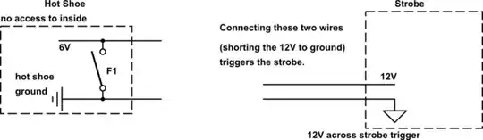
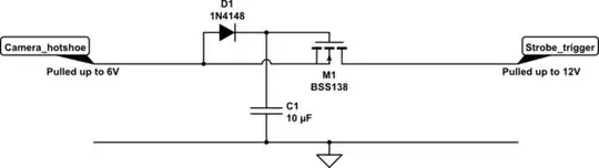
I need to trigger a strobe from a Sony Hot Shoe.

A 3.5mm jack lead comes out of the hot shoe. Using a multimeter I measured 6V across the tip and sleeve of the jack, and when the camera triggers the ring and tip become connected like a switch closing.

Two wires come out of the strobe. Using a multimeter I measured 12V across them. When you touch them together, the strobe triggers.

If I connect the hot shoe to the strobe, it all works fine. When the camera triggers the ring becomes connected to the sleeve completing the circuit and effectively shorting the strobe trigger to ground and firing the strobe.

The problem is that when I plug the camera into to a PC through USB, the strobe stops working. Cutting the power wires on the usb does not fix this, but cutting one of the data wires does. We have assumed that the hotshoe circuitry must be somehow connected to the USB circuitry.

Off-the-shelf flashes work with the USB connected, but they also have 12V across the trigger leads, so we assume that off-the-shelf flashes are opto-isolated. We are hoping that opto-isolating the strobe trigger will fix the USB issue.

The ideal solution

schematic

simulate this circuit

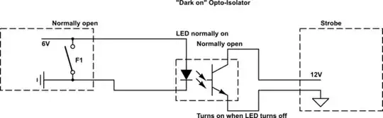
Because there is normally 6V out of the hot shoe, and this goes to 0V when the short is created, the LED in the opto-isolator will normally be on. Therefore I need a opto-isolator that lets the phototransistor allow a current to flow when the LED is off, and stops current when the LED is on. Does this type of "dark on" opto-isolator exist, and what should I search for to find one?
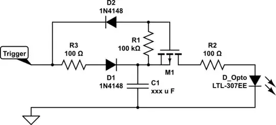
Alternatively

schematic

simulate this circuit

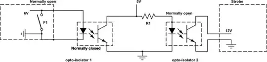
If a "dark on" opto isolator doesn't exist, my idea is to use two optoisolators. The opto-isolator 2 will be powered from a separate 5V voltage source, that will be shorted out when opto-isolator 1 is closed. (i.e, no current will flow through R1 because there is a short to ground through opto-isolator 1). The problem is this requires a new separate power supply, and i'm unsure if it will work. Will this work and is there a better way to do it?

Thanks!

Blue7
  • 1,635
  • 6
  • 24
  • 33
  • Not sure if this helps but I don't think the Nikon is really supplying 6V at any meaningful current, it'll be a simple pull to ground. See this answer I posted a while ago: http://electronics.stackexchange.com/a/75756/17064 – PeterJ Jun 21 '16 at 14:52
  • Obviously, cutting one of the data wires in the USB cable means that the camera is no longer logically connected to the camera. So disabling the flash would seem to be a logical function inside the camera, and electrically isolating the hotshoe connection will have no effect. Instead, you should be looking at the configuration menus for the camera to find a setting that will allow the flash to work even when the USB is connected. I haven't worked with Nikon cameras. I can tell you that on the Canon cameras that I use for aerial photography, the hotshoe works just fine with USB connected. – Dave Tweed Jun 21 '16 at 15:21
  • @Dave Tweed That was our first thought, but any other off-the-shelf flash works fine when the camera is connected to the computer. It is only the strobe that doesnt work in this situation, which is why we want to modify it by adding opto-isolators – Blue7 Jun 21 '16 at 15:44
  • @PeterJ Thanks. I read that post before asking this question. I know the current limitations of the hot shoe will be small, but I think it should be enough to drive an opto-isolator – Blue7 Jun 21 '16 at 15:46
  • @Dave Tweed. Also, by using an opto isolator it prevents connecting the 12V from the strobe to the camera. As you said, usually you can connect the 12V wires from a flash to a hotshoe and it will still connect to a PC through USB without a problem. I'm assuming that these flashes are not capable of delivering a significant amount of current through the flash leads back to the camera, but my strobe can, and therefore needs opto-isolating. – Blue7 Jun 21 '16 at 16:02
  • Your 'alternatively' circuit isn't correct. Opto 1 transistor will short out the intermediate supply when it's turned on and will die. It should be wired across the LED of Opto 2 to steal its current. See my answer below for a simpler solution. – Transistor Jun 28 '16 at 00:00
  • Hi @Blue7, were you successful with this? – James Apr 20 '17 at 05:28

3 Answers3

2

schematic

simulate this circuit – Schematic created using CircuitLab

Figure 1. A very simple opto-isolator with normally-off output.

How it works:

  • D1 allows C1 to charge up from the 6 V supply. See note on current limiting below.
  • When the strobe contact closes D1 is reverse biased and C1 discharges through R2, D2 and SW1. With R2 = 390 \$\Omega\$ the current will be limited to 10 mA.
  • While the LED is on Q1 will 'close its contacts'.

The beauty of this apart from its simplicity is that the LED is normally off, saving power.

Current limiting

We don't know exactly what is protecting the 6 V supply. I suggest you connect a 1k resistor across the jack and measure the voltage across it. From that you can calculate the voltage drop internally and figure out the effective series resistance. If this is less than 1k (indicated by > 3 V across the test resistor) then I'd be inclined to add a 1k resistor between D1 and the top of C1 to limit the surge current on connection.

Transistor
  • 168,990
  • 12
  • 186
  • 385
1

That was our first thought, but any other off-the-shelf flash works fine when the camera is connected to the computer. It is only the strobe that doesnt work in this situation, which is why we want to modify it by adding opto-isolators.

In that case, you can probably get by with a much simpler level-shifter, like this:

schematic

simulate this circuit – Schematic created using CircuitLab

This works just like the common 3.3V-to-5.0V level shifters seen on I2C busses, except that we need the diode and capacitor to capture and hold the gate bias during a trigger event. The MOSFET allows the hotshoe to pull the strobe trigger low, but prevents the 12V pullup from the strobe from back-feeding the camera.

Dave Tweed
  • 168,369
  • 17
  • 228
  • 393
  • That's very interesting, thank you very much! I'll try this in the morning. Can you please explain why you think it needs a level shifter? – Blue7 Jun 21 '16 at 17:45
  • Not really. I'm guessing that either the 12V pullup from the strobe is affecting the camera logic or the 6V pulldown from the camera is affecting the strobe, but I can't explain why this only happens when USB is attached. Perhaps the USB power pulls the "6V" to a lower level than it has without USB, which puts it below some threshold for the strobe. But whatever the reason, this kind of isolation should fix it. – Dave Tweed Jun 21 '16 at 18:42
1

The circuit shown below appears to meet the specific need.
It does not allow ongoing drive of the optocoupler LED but does provide a pulse to the LED when the input trigger line is taken low.

This circuit is 'out of my head', may well work 'as is' but also may need some refining.

Operation:

C1 stores energy from the input which is used to drive the LED when the trigger line is taken low.

With Vtrigger high C1 charges via R3 and D1.

  • R3 may not be needed - it is provided to minimise the load of the initially uncharged capacitor on the trigger line.

  • D1 prevents discharge of C1 during triggering, allowing energy to be saved for the next initiation and preventing possible adverse effects from C1 discharging into trigger input.

  • If length of trigger low is shorter than desired (unlikely but possible) the FEt on time can be extended by adding a suitable capacitor Cg from M1 gate to ground such that the time constant of R1.Cg holds the FET on as desired. MOSFET M1 is held off by R1 when Vtrigger is high.

When Vtrigger goes low M1 is turned on by D2 to gate.
LED is operated by discharge of C1 via R2.

  • R2 may not be necessary - it limits current to the LED and prolongs the discharge time of C1. The sizing of C1 and R2 depend on the length of the trigger pulse and the optocoupler characteristics.

schematic

simulate this circuit – Schematic created using CircuitLab

Notes:

Values shown for R2, R3 are arbitrary and need to be designed to suit.

MOSFET needs to have suitable Vgsth so that available turn on voltage is sufficient.

MOSFET can be driven by a comparator for sharper on/off drive.

Russell McMahon
  • 147,325
  • 18
  • 210
  • 386