-4

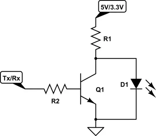
How would i go about connecting indicator LEDs to the serial lines from my MCU(a Parallax Propeller) to a MAX3232 and the chip select line for a SD card? I want the LEDs to light up when the lines are low, as all the signals are active-low. Everything is running at 3.3V, but a 5V supply is available. The SD select line is pulled to 3.3v by a 10k resistor (this is according to the documentation of the SD driver), the serial is just straight from MCU to MAX3232 (should i pullup TX aswell? It could be configured as input by software when its not used)

Im doubting the viability of connecting them directly from the lines to 5v or 3v, as they might be running at 100's of Khz and i have heard the MAX3232 isn't exactly good at running lots of current through its I/O lines (the datasheet doesn't seem to say anything about that).

If my worries are justified, i would prefer a solution with through hole components. Also, if possible, i would like to run the LEDs off the 5V supply to reduce load on the 3.3v regulator and use posssibly use LEDs with forward voltages close to or higher than 3.3v.

  • 1
    Please use the schematic tool and post a schematic. You also need to ask a question, http://electronics.stackexchange.com/help/how-to-ask If you wish to re-open the post, add a question and more info like a schematic. – Voltage Spike Jun 20 '16 at 20:33
  • There is a question, and i don't think a schematic is nercassy to explain the situation – Wuerfel_21 Jun 20 '16 at 20:52

2 Answers2

1

Try this:

R1 has been sized assuming a typical green LED with 2.1 V drop and 10 mA of LED current when the digital signal is low.

When the digital signal is high (at 3.3 V), there will be about 1 V across the LED. This will make it light very very dimly. You will probably be able to see it lit in a dark room, but probably won't notice it in typical office illumination.

When the base of the transistor is low, most of the current entering the emitter will go out the collector, not the base. The gain will be somewhat lower due to the C-E voltage only being the B-E voltage when on, but there will still be significant gain. Even if the gain is only 10, for example, that still means that 91% of the LED current will go thru the collector, with the digital output only required to sink the remainder.

For completeness, here is how to do this with positive logic:

The resistor has again been sized for a 2.1 V LED at 10 mA. I reality, even 10 mA is quite bright for a indicator. I typically use 100 Ω for R1, which results in about 5 mA. That's actually quite bright in regular office illumination when looking directly at a modern green LED in 0603 package.

In this case, the transistor is run well into its linear region, so you can expect the full gain at whatever you set the LED current at. That puts even less load on the digital signal. For example, with 5 mA LED current and a gain of 50, the digital output only has to sink 100 µA when high. That's the same as a 33 kΩ resistor to ground when at 3.3 V.

Olin Lathrop
  • 310,974
  • 36
  • 428
  • 915
0

How about a transistor inverter, like this one? You can alternatively replace R2 and Q1 with a MOSFET, but you'll want to make sure that the gate capacitance won't affect the rise or fall times on your data lines.

schematic

simulate this circuit – Schematic created using CircuitLab

justinrjy
  • 764
  • 4
  • 7