-4

My study field was computer and I'm a newbie in electronics.

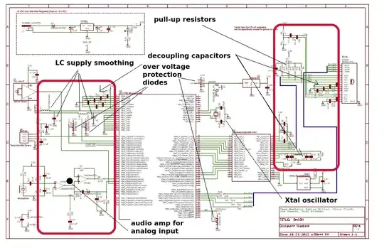
I want to build a microcontroller based board (I think it is called an MCU board?) and when I search for example, how to interface lpc1768 with sensors, motors, Ethernet or USB port, etc, I will find many schematics like what I've added to my post.

I know we can not directly connect motors or sensors to microcontrollers only with 2 or 3 wires! It should be some circuits or electrical elements(resistor, capacitor, inductor, etc) between them like what I attached in post.

My main question is here: what are these? how can I learn them? how to design them for my projects? how they work? and any more questions to understanding and learning them....

Is there a book or course to learn them?

enter image description here enter image description here

Null
  • 7,448
  • 17
  • 36
  • 48
arash
  • 7
  • 3
  • As it is, I'm afraid your question is too broad/unclear. You've highlighted half the components here. And we can't even read the schematic. And we don't know what this system does. You can learn this by starting to look at simpler schematics, trying to understand things little by little. And when asking questions here, trying to be more specific. Focus on a single part of the schematic, after having figured out what each block was more or less doing. – dim Jun 14 '16 at 08:51
  • In the first image, you highlighted the capacitors across VDD and GND, which are power supply bypass capacitors, essential to making a practical PCB design work. Every digital IC uses them. Related: http://electronics.stackexchange.com/questions/15135/decoupling-caps-pcb-layout/15143#15143 – MarkU Jun 14 '16 at 08:52
  • In the second image, you've highlighted what appear to be either op-amps or comparators. Horowitz/Hill **Art of Electronics** chapter 4 would be a good place to start. – MarkU Jun 14 '16 at 08:52
  • Start with something like a pre-built arduino to practice with - its easy to program and there are lots of projects on the net which explain how to interface various sensors (sound,heat,light etc.) and actuators (motors, solenoids,relays etc.). It really doesn't matter what the processor is as you are learning about interfacing. – JIm Dearden Jun 14 '16 at 08:55
  • That's like saying here's a complicated program in C, tell me what each line does. – Chu Jun 14 '16 at 14:58

2 Answers2

0

In answer to the 'what are these circuits'

enter image description here

The audio amp is made up from op amps (low voltage version LM358?)

JIm Dearden
  • 18,926
  • 30
  • 40
  • Oh thanks a lot Jim, this is what exactly I want. but not only for this specific pic. I want to learn them and then I can understand and designing them for any projects and Micros. So is there a book or some books to learn them (pull-up resistors, decoupling capacitors, over voltage protection diode, etc) .... How can I learn them??? – arash Jun 14 '16 at 09:28
  • see my comment above - get yourself an arduino and built some projects with that. If you blow it up in the process its not an expensive mistake. Interfacing is basically the same for every other processor - its either digital I/O or an analog port. Most processors operate either at 3V3 or 5V. As my old tutor used to say - From the concrete to the abstract. Learn by doing, and walk before you try to run. – JIm Dearden Jun 14 '16 at 09:38
  • Thank you Jim, but I'm trying to learn about hardware interfacing and electronics side. I think arduino is something like STM32 discovery board(tell me if I'm wrong) and it's about learning the programming of a Microcontroller. but I do not like that, I am looking for hardware side and interfacing a Microcontroller on the board. – arash Jun 14 '16 at 10:06
  • The stm32 is an ARM chip, the arduino is an ATMEGA but you can basically **use any microcontroller you like**. Interfacing is a **combination** of the software and hardware. The internet is full of suitable projects and explainations - do some research. – JIm Dearden Jun 14 '16 at 10:35
  • So give me some topics or keywords that I should search for it to learn basic rules and concepts of interfacing(I mean pull up resistors, coupling capacitors, voltage protection diodes, amplifiers, supply smothers and "other things those are important to know but there aren't in this pic!") – arash Jun 14 '16 at 10:51
0

LPC1768 is way too complicated for your expertise level, I think. Let's talk about Atmega328 (the backbone of arduino UNO and many others).

Short answer: RTFM

Long answer: There is no magic book which you can read and become a master in these concepts. After you have learnt about the basic electronics, you need to start working and finding your way out. This will teach you a lot.

Step 1: Download the datasheet

You need to download the datasheet of the micro-controller you wish to work with. Get to know what are the capabilities of the micro-controller, what power supply it needs for functioning, what external components are required for it to work etc. For example - Atmega328 needs a pullup resistor at RESET pin, preferably with a protection diode. It can run from 1.8V to 5.5V DC power supply. It's preferable to give decoupling capacitors at VCC pin. If you need higher clock speed, you need to add external clock source, in which case, you need capacitors on crystal as well. This gives you a minimal circuit as shown below:
Minimal atmega328

This is a working circuit ready to accept code.

Step 2: Figure out what other hardware do you need to program it and make your project.

Once your barebone micro-controller circuit is done, you need to attach the remaining hardware and program it. Atmega328 can be programmed using SPI based programmer. Alternatively you can use an Arduino board to program it. All this info is available on the internet. Once programming hardware is fixed, you need to figure out the sensors or actuators that you are interested in. Whether your motor runs on same voltage as micro-controller, how much current it draws, what motor driver you require... this list is endless and depends upon what exact components you are using. For the sake of simplicity, lets assume you are using an analog temperature sensor which gives you a voltage proportional to the temperature. For this, get the datasheet of the sensor and figure out the circuit you need - which pin needs to be connected to VCC and GND etc. There will be an output pin which you need to connect to ADC pin of atmega. Open the atmega datasheet (yes, again) and find out which pins have that capability. Complete the circuit.

Step 3: Programming

Once you are done with making the complete circuit, write the code and dump it into the micro-controller. You need to decide the logic for writing the code. Logic will depend upon the info provided in the datasheets of sensor (so open it and read it again).

Step 4: Debugging

Your project doesn't work as expected? It happens to most of us most of the time. Look for bugs in your code and hardware. Try to narrow down the issue. Ask us if you are not able to figure it out but don't post questions like - "My circuit is not giving output, what should I do?". You need to be precise about your questions so that a third person can understand and come up with some valid answer.

Whiskeyjack
  • 7,946
  • 8
  • 53
  • 91
  • Thanks a lot Jack! You are true and I can not learn all the electronics in one book, but how about basic concepts(pull up resistors, coupling capacitors, etc)? something like what Jim written in the pics? is there a good book to start? – arash Jun 14 '16 at 10:07
  • Practical electronics for inventors seems like a good start. – Whiskeyjack Jun 14 '16 at 12:34