-2

I have a 7.5V, 2A, Radio Shack AC adapter and I need it to be a 7.5V, 1.5A power supply. It has one of those tip-ring style plugs on the DC end that plugs into a device to provide power.

I need the wall-wart to be incapable of delivering more than 1.5A or else it will damage the piece of equipment being used -- I'm not 100% sure why the damage occurs but I do know that battery charging inside a 22-year-old laptop is involved.

So my plan is to wire a 5Ω resistor in between the wall wart and the DC plug on the positive wire. That way the current will drop down to 1.5A. The electricity flowing across the DC terminals on my electrical simulator program, iCircuit, shows indeed 7.5V and 1.5A.

But my friend says that this is wrong, that the resistor will also make the voltage drop. Is he right?

Side question: how do I represent the AC/DC adapter correctly in my circuit simulation program? Because it has current sources and voltage sources, but not both. I tried actually building a circuit in there for an AC/DC adapter and it worked, but I feel like I was making it overly complicated.

I don't understand how there can be a current source that has no voltage.

clabacchio
  • 13,481
  • 4
  • 40
  • 80
Dark Goob
  • 137
  • 6
  • 1
    How many questions about voltage/current limit are we going to get before we start closing them as duplicates? – Kellenjb Dec 22 '11 at 12:08
  • 1
    possible duplicate of [Reading and understanding electrical specs on laptop AC adapters](http://electronics.stackexchange.com/questions/11252/reading-and-understanding-electrical-specs-on-laptop-ac-adapters) – Kellenjb Dec 22 '11 at 12:14
  • You are at risk of having this closed (not by me). I suggest you try and answer my latest questions asap (Accurate schematic or photo as what you are doing CANNOT do what you say you want. If it works for you that's good, but it means you are doing something other than you say or the equipment is working differently than you describe. A bad outcome is the most likely one. [Believe me or not as you see fit - but I strongly recommend unquestioning belief in this case, before the kneecapping crew arrive :-) - RM] – Russell McMahon Jan 16 '12 at 18:32
  • Russell: here's a link to the video where I wired the resistor on the negative wire (as opposed to the positive one, which is what I had put in the original post): http://www.youtube.com/watch?v=JUEjKDBOQYw&feature=youtube_gdata_player ... Don't break my kneecaps! I just don't understand why people think this is impossible (what I did in the video). I am sorry if i am missing something here, but i thought ohm's law was Current = Voltage / Resistance, so if you change the resistance then you change the current, which is exactly what I did. Why is this a problem involving kneecapping? – Dark Goob Jan 17 '12 at 00:05
  • The kneecapping crew referred to those who vote questions down and close them while in the process of discussion because the question is deemed inappropriate. In this case I see we are getting somewhere so hopefully we will be allowed to work through this.| Please take the following as intended. The video was great as it showed how you are connecting things, where you are measuring and when and what yuou think it show you. I sat there throughout with a large grin as it all came clear - it was about as I expected but now we can sort it out. – Russell McMahon Jan 17 '12 at 10:46
  • I like your enthusiasm and willingness to have a go. But/and you have made some significant incorrect assumptions. That matters not as now we know what they are. I have 2 jobs to do & may have to sleep before I can answer. I'll go do one job and come back and give an interim reply. But - | Your solution will not work withe your laptop unless it draws very little current AND can run on low voltage. |A resistor **will** drop voltage when current flows through it. V = I x R . If you get a 2nd meter and measure V at either end of R while playing much will become clear. More soon. – Russell McMahon Jan 17 '12 at 10:52
  • OK, I will await your further response... so far my understanding is that Voltage is a measurement in the difference in potential EMF between two points (EMF being the ability to move current thru a resistor). That's the logic I based my assumptions on... am I wrong? – Dark Goob Jan 17 '12 at 17:41
  • Above IS my response. YOU have the ball. Get a second meter. Measure V and I at once and you will instantly see what is happening. You are making two NON INDEPENDENT measurements not at the same time and varying the conditions between measurements. Shorting the output to test Iout reduces the Vout to 0V. The laptop would not run. You can get V or I with what you have done but not both. Clue" Everywhere that you say "obvious", of course" logical etc. delete them and then see if you can see why the situation is NOT as you say.. Read what I and others have explained - its all there. – Russell McMahon Jan 20 '12 at 07:46
  • Well I don't have the extra cash for another meter right now. But I am still not sure how, exactly, the meter could show it's the correct voltage and amperage and yet, be wrong. I mean, it makes sense that the 5Ω resistor would drop current down to appx. 1.5A since that's as much current as 7.5V can push through a 5Ω resistor. And yes, I realize that after the EMF is done pushing that 1.5A through whatever resistance the laptop entails, then afterwards there will be no more voltage left because the power will have all been converted to heat, motion, etc. Am I right or wrong? – Dark Goob Jan 21 '12 at 07:06

3 Answers3

6

The current rating of the wall-wart doesn't mean it will deliver X amps, it means it's capable of sourcing X amps. The actual current flowing through the circuit is dependent on the voltage and the load you're supplying. As long as the voltage is appropriate for the load, you could use a 7.5VDC / 398A power supply and it wouldn't make any difference. The load will "pull" the current that it pulls at that voltage... more current won't just magically flow because it's available.

More info on what you're trying to do would probably help...

That way the current will drop down to 1.5A

Resistance will cause a voltage drop. The voltage drop in turn means that less current will flow. But, again, you don't need to go arbitrarily adding extra resistance in series with a load to reduce the current, if you're supplying it with a power supply that's rated for the correct voltage. If you're not working with some discrete load that has a predetermined current / voltage spec, then you just need to apply ohm's law and figure out what current will flow through your circuit at the selected voltage.

mindcrime
  • 1,108
  • 8
  • 11
  • Ok, I know what you said is true, however this is a special case... I said don't ask why. The main reason is that trying to answer WHY I need this, will not get me any closer to an answer to my actual question. But it will require a lot of explaining and sidetrack the question. – Dark Goob Dec 22 '11 at 07:23
  • But, suffice it to say, I need the wall-wart to be incapable of delivering more than 1.5A or else it will damage the piece of equipment being used -- I'm not 100% sure why the damage occurs but I do know that battery charging inside a 22-year-old laptop is involved. – Dark Goob Dec 22 '11 at 07:31
  • 1
    OK, if you definitely need a current regulated circuit, you could try using an LM317 adjustable regulator, configured as a current regulator. I have never used this scenario, so I can't do much more than point you at the docs, and/or say that hopefully one of the more experienced members here will chime in. http://www.national.com/mpf/LM/LM317.html#Overview is an overview, and this doc is specifically about using the LM317 in a battery charging scenario: http://www.ti.com/lit/an/snva581/snva581.pdf – mindcrime Dec 22 '11 at 07:36
  • So I take it that simply placing the 5Ω resistor won't limit the current? Why is my circuit simulator lying to me? – Dark Goob Dec 22 '11 at 07:40
  • PS -- the device being connected is a laptop that PC World rated as the 17th-worst tech product of all time, a "beast" that could not run off of AC power. Its manufacturer says using a power supply with too much wattage can damage the board, even though all their power supplies at the time were the same voltage! – Dark Goob Dec 22 '11 at 08:16
  • @user7154 Can you post the simulated circuit? There may be something wrong with it. Also note that voltage and current sources you've mentioned in the question don't exist in real life. They're just used to model the circuit and to get realistic behavior more components are needed. All voltage sources have internal resistance which will affect output voltage as the current increases and all current sources have internal conductance which will affect output current as the voltage increases. – AndrejaKo Dec 22 '11 at 09:17
  • 3
    Also I may sound unfriendly, but due to complexity of what you want and due to amount of knowledge you've shown, I'm afraid that to your `don't ask why` I must respond with `don't ask how`. – AndrejaKo Dec 22 '11 at 09:19
  • @user7154 Current and Wattage ratings on power supplies for laptops are the maximum that can safely be pulled from them, but the don't necessarily prevent pulling more current then what they are rated for. Most likely this laptop that you talk about either has its battery charging circuity out side of the laptop itself or it has a data line that it negotiates what power it is allowed to pull and the laptop has some internal issue when it tries to charge itself faster. – Kellenjb Dec 22 '11 at 14:10
2

Your solution would cause voltage drop. Current through a series resistor MUST drop voltage.
You must be using iCircuit incorrectly,
or wrongly reporting what you really did
or the program is faulty.

The first two choices are the most likely :-).


Placing a 15 ohm resistor ACROSS the supply output so it shunts 500 mA (I V/R = 7.5/15 = 0.5A) would work IF the supply really was a 7.5V, 2A supply.

BUT it almost certainly won't be.
Some supplies are voltage regulated and it may make a reasonably accurate 7.5V. BUT very very few supplies are designed to supply a certain current and no more. The spec "2.5A" usually means "will provide at least 2.5A at an output voltage that not too many buyers will complain about.

FWIW "why" almost certainly helps. Most people asking questions miss things sometimes (and that certainly includes me) and providing as much "why" as possible allows people to see unexpected things that may affect the answer.


Best solution is to crush the laptop or give it to someone who is damaging the world, or pit in a museum collection. That last suggestion may be a good one in due course if not immediately.


Next best is to obtain a supply that meets your spec.

Easiest and quickest (as opposed to best or cheapest etc) is to buy or uses a "lab supply" that you adjust current an voltage on as required. IF you can afford this it is a very good solution (as long as portability is not a must) as you then have an extremely useful supply for other uses.


Or make one - not very hard and not too too dear.

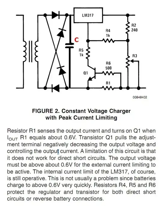
A good, easy and cheap (choose any 3) solution is in the Useful LM317 battery charging application note that @mindcrime referred to.

Their fig 2 does what you want albeit somewhat crudely.
The LM317 sets the output voltage and Q1 and R1 etc limit max current.
Be sure that your brand of LM317 will supply 1.5A. It varies.
Changinge the LM317 to an LM350gives more current.
Note that this circuit needs to be fleshed ou t - eg a filter cap where I show and one at the output and maybe one on the reference pin.
See LM317 datasheet.

enter image description here


Even easier is to use an LM317 in constant current mode, as in their fig 4, thusly

enter image description here

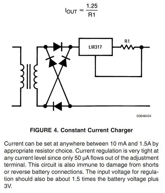
And THEN follow this with an LM317 based 7,7V supply. Note their comment on required Vin.

Total solution takes 2 x LM317 + resistors + capacitors and it does exactly what you have asked for.

Vin needs to be about 7.5V + 2.75 V + 1.25V + 2.75V =~ 15 VDC

This surprisingly high amount is because the LM317's have a dropout voltage of up to 2.7%V at .5A and the current source also drops 1.25 extra.

Hear sinking will be needed. eg L317: 2.5V x 1.5A = 4+ Watts.

A 12VAC transformer will give enough voltage .
A 10 VAC transformer MAY give enough voltage.
Or a 1.5A+ x 15V+ power supply can be used.


An attempted solution

User says:

  • I measured the voltage at the negative and positive terminals of the DC output of the AC adapter, without modification it read 2.02A/7.86V.

  • Then I wired a 5Ω resistor to the negative output and measured the new readings. Still 7.86V, but amps dropped to 1.42

  • It was real world. The resistor was put between the negative wire comimg out of the wall wart, and the sleeve part of the plug that goes into the laptop.

I understand the circuit to be:

  • Adaptor +ve to Laptop + in
    Laptop - out to resistor one side
    Resistor other side to adaptor -ve.

I'll use WW (= Wall Wart) for "adaptor" below.

You say voltage is 7.86V BUT not if this is at PC or WW.
BUT as you say it did not drop it was probably at WW, but not necessarily.

As you have used a 5 ohm resistor and as you report 1.42 Amp then the drop in the resistor is given by Ohms law as
V = I x R = 1.42 x 5 = 7.1 Volt.

This makes no sense.
If the current from thw WW is flowing through the resistor to the laptop, then laptop voltage is 7.86-7.1 = 0.76V.

If the resistor is not in fact in series but in parallel with the WW then it is carrying about I = V/R = 7.86 / 5 = 1.57A.
So if the 1.42A reported is not the current through this resistor it should be the current through the laptop so total adaptor current = 1.57+1.42 = 3A.

The only other choice is that the re[ported voltage is measured at the laptop, in which case the voltage at the adaptor must be 7.86 + resistor drop = 7.86 + 7.1 = 15 V.

ie the result appears wholly wrong. A 0.5 ohm resistor may explain things. Or not.

So alas, yes please. Either please provide a clear diagram or a clear well focused photo. Also please show or describe what voltages are where.

This may all seem like making much out of little *(and it is) BUT what you have described so far WILL NOT meet your stated need. It may in some way meet and actual need, but that means there are things we have not been told.

Russell McMahon
  • 147,325
  • 18
  • 210
  • 386
  • I *think* iCircuit is probably working okay - I suspect the 5 ohm resistor is simply being placed directly across a 7.5V source (i.e. 7.5 / 5 = 1.5) rather than to a load, and the voltage measured from the positive terminal of the source. Of course this would probably fall into the category of "using iCircuit incorrectly" :-) – Oli Glaser Dec 22 '11 at 11:27
  • Oli- I measured the voltage at the negative and positive terminals of the DC output of the AC adapter, without modification it read 2.02A/7.86V. Then I wired a 5Ω resistor to the negative output and measured the new readings. Still 7.86V, but amps dropped to 1.42 -- pretty much exactly what I was trying to achieve. Simple logic prevails. – Dark Goob Jan 15 '12 at 21:17
  • 1
    @user7154 - Your statement is not complete and so your meaning is completely unclear. You say "I wired a 5 ohm resistor to the negative output" BUT (1) you don't say where the other end went. ie If in series with the load (probably what you meant) or if across the adaptor. and (2) You don't say if the wiring was done in a simulator or with a real world device. If done with a simulator the result is worse than useless as it gives no indication of the real-world outcome as it NECESSARILY drops output voltage, which you probably cannot tolerate. My December 22nd answer provides what you NEED. – Russell McMahon Jan 16 '12 at 00:54
  • It was real world. The resistor was put between the negative wire comimg out of the wall wart, and the sleeve part of the plug that goes into the laptop. Want me to post photos/videos? – Dark Goob Jan 16 '12 at 08:00
  • 1
    @user7154 - I've been through your figures and alas they "do not compute". So alas, yes please. Either please provide a clear diagram or a clear well focused photo. Also please show or describe what voltages are where. What is voltage at either end of resistor compared to wall wart -ve output when operating? This may all seem like making much out of little *(and it is) BUT what you have described so far WILL NOT meet your stated need. It may in some way meet and actual need, but that means there are things we have not been told. – Russell McMahon Jan 16 '12 at 12:31
  • So having watched the video, what do you say? – Dark Goob Jan 20 '12 at 02:40
0

The last part of your question, concerning the difference between (ideal) current sources and (ideal) voltage sources is key to understanding the whole thing.

Your typical regulated power supply is an approximation to a voltage source. It delivers a steady voltage nearly irrespective of varying current draw - until some maximum current is reached, at which point the fact that is a real device and not an ideal voltage source will become apparent in one way or another (sagging voltage, complete shutoff, smoke, etc).

Occasionally (as a mode of operation on bench supplies, as a block within certain analog circuits, certain types of welding power supplies, etc) you find power supplies that are an approximation to a current source. Their output voltage will increase to push the rated current through the load, up to some limit voltage at which they cease approximating a current source. Sometimes this is actually secondary to voltage regulation, in that both the current and the voltage are regulated to a limit - if the current drawn by the load increases, the voltage drops.

Finally there are unregulated supplies where voltage varies with load current. These are often simple transformer-rectifier-filter affairs, and may produce more than the nameplate voltage when only lightly loaded.

As for modeling, if your supply is voltage regulated, you probably want to use a voltage source and verify by measurement in the simulation that you do not exceed the current rating. Some manufacturers provide more accurate simulation models for specific regulator ICs.

If your supply is unregulated, you may be able to approximately model it with a Thévenin equivalent circuit, consisting of an ideal voltage source with a series resistor, which models how the voltage drops with load current (though this would not model the AC ripple behavior also present in many cheap unregulated supplies). Alternatively, you can use the Norton equivalent circuit consisting of an ideal voltage source with a resistor across its output - mathematically demonstrating the equivalence of the Thévenin and Norton models is a typical exercise in a first year EE circuits course.

Chris Stratton
  • 33,282
  • 3
  • 43
  • 89