5

Enter image description here

I am working on a university project in which I need to interface a PIC18F4550 with an I²C EEPROM.

I read many codes and saw many projects on this topic. And I wrote a sample code from MPLAB C18 (and I tried many codes also), but no one worked with me.

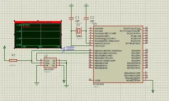
I don't know where the problem is. Everything is OK with my code and with my circuit, but the SCK signal did not generate the CLK signal for writing and nothing has been written to EEPROM.

Here is the code:

#include "p18f4550.h"
#include "i2c.h"
#pragma config FOSC = HS
#pragma config PWRT = OFF
#pragma config BOR = OFF
#pragma config MCLRE = ON
#pragma config PBADEN = OFF
#pragma config ICPRT = OFF
#pragma config LVP = OFF
#pragma config WDT = OFF,DEBUG=OFF

unsigned char arraywr[] = {1,2,3,4,5,6,7,8,0};
unsigned char arrayrd[20];
//***************************************************
void main(void)
{
    OpenI2C(MASTER, SLEW_ON);// Initialize I²C module
    SSPADD = 10; //400 kHz Baud clock(10) @20 MHz
    while(1)
    {
        EEByteWrite(0xA0, 0x30, 0xA5);
        EEAckPolling(0xA0);
        EECurrentAddRead(0xA0);
        EEPageWrite(0xA0, 0x70, arraywr);
        EEAckPolling(0xA0);
        EESequentialRead(0xA0, 0x70, arrayrd, 20);
        EERandomRead(0xA0,0x30);
    }
}

This is the code of OpenI2C:

    /* $Id: i2c_open.c,v 1.1 2004/10/06 23:16:42 curtiss Exp $ */

    #include <p18cxxx.h>
    #include <i2c.h>


    /********************************************************************
    *   Function Name:  OpenI2C                                         *
    *   Return Value:   void                                            *
    *   Parameters:     SSP peripheral setup bytes                      *
    *   Description:    This function sets up the SSP module on a       *
    *                   PIC18CXXX device for use with a Microchip I²C   *
    *                   EEPROM device or I²C bus device.                *
    *********************************************************************/
    void OpenI2C( unsigned char sync_mode, unsigned char slew )
    {
        SSPSTAT &= 0x3F;                // Power on state
        SSPCON1 = 0x00;                 // Power on state
        SSPCON2 = 0x00;                 // Power on state
        SSPCON1 |= sync_mode;           // Select serial mode
        SSPSTAT |= slew;                // Slew rate on/off

        #if defined(__18F2455) || defined(__18F2550) || \
            defined(__18F4455) || defined(__18F4550)

            DDRBbits.RB1 = 1;           // Set SCL (PORTB,1) pin to input
            DDRBbits.RB0 = 1;           // Set SDA (PORTB,0) pin to input

        #else

            DDRCbits.RC3 = 1;           // Set SCL (PORTC,3) pin to input
            DDRCbits.RC4 = 1;           // Set SDA (PORTC,4) pin to input

        #endif

        SSPCON1 |= SSPENB;              // Enable synchronous serial port
    }
bouqbouq
  • 583
  • 8
  • 27
m_engineer
  • 51
  • 1
  • 4

2 Answers2

1

Everything can't be okay with your code and circuit if SCK is not generating a clock ;-)

(Note that SCK is for SPI. SCL is the name for the I2C pin. So below the reference to SCL is what you are calling SCK)

This could be as you haven't configured the pins properly as Leon mentions, or possibly as you haven't added pullup resistors to your SDA/SCL lines.

If you show your circuit (or just let us know if there are pullups present) and any I2C initialisation code (e.g. what happens in OpenI2C) we can confirm what the problem is.

EDIT - Looking at your schematic it looks like you have no pullup on SCL, which would account for nothing being seen on it. The I2C lines are driven using open drain outputs, which means the pin can only sink current, not source it.
If you add a resistor (say, 2k to 10k) from SCL to Vdd you should see something.

EDIT 2 - I'm not sure where it says no pullup is needed on SCL. I just had a look in the datasheet and I found this (page 207):

Selection of any I 2 C mode with the SSPEN bit set forces the SCL and SDA pins to be open-drain, provided these pins are programmed as inputs by setting the appropriate TRISC or TRISD bits. To ensure proper operation of the module, pull-up resistors must be provided externally to the SCL and SDA pins.

Are you using a real PIC here or simulating things in ISIS? If it's a simulation then it may be something do to with how it's setup.
Have you got the TRIS bits set accordingly? (both to 1)
Also for good measure, set the ADCCON1 registers bits 3:0 all to 1, to set all the pins as digital. You can do e.g. ADCCON1 |= 0x0F; for this.

Oli Glaser
  • 54,990
  • 3
  • 76
  • 147
  • Oli, I have edited my post and added the image. please check it. Thanks :) – m_engineer Dec 21 '11 at 21:01
  • Also, I have added the OpenI2C function now. – m_engineer Dec 21 '11 at 21:11
  • @m_engineer - Okay, see edits - I can't see a pullup on SCK. – Oli Glaser Dec 21 '11 at 21:33
  • According to the datasheet, there is no need to have pullup on SCK. But, I tried to have pullup and nothing have been changed ! – m_engineer Dec 21 '11 at 21:57
  • @m_engineer - Where did you see this? – Oli Glaser Dec 21 '11 at 23:32
  • For the scl, I read the following from the data sheet 2.3 Serial Data (SDA) This is a bidirectional pin used to transfer addresses and data into and data out of the device. It is an opendrain terminal, therefore, the SDA bus requires a pullup resistor to VCC (typical 10 kW for 100 kHz, 2 kW for 400 kHz and 1 MHz). For normal data transfer SDA is allowed to change only during SCL low. Changes during SCL high are reserved for indicating the Start and Stop conditions. 2.4 Serial Clock (SCL) This input is used to synchronize the data transfer from and to the device. – m_engineer Dec 22 '11 at 20:25
  • @m_engineer - I can't see where it says no pullup is needed there. I2C always uses open drain + pullups for both lines. Can you test the PIC is working at all by doing something like toggling a pin? Are you simulating this or using a real PIC? – Oli Glaser Dec 23 '11 at 00:13
  • R1 is placed in the current schematic, but it has no value. It is essentially not there. – rdtsc Jun 17 '15 at 20:26
0

You need to configure the pins that are used for the I2C interface for input/output. Input pins that are shared with analogue inputs need to be set as digital inputs.

Leon Heller
  • 38,774
  • 2
  • 60
  • 96