3

I need to drive a 12m strip of APA102 RGB LEDs (144 per meter). I use a Raspberry Pi for this Job.

This LED driver IC (APA102) takes an SPI signal and hands it to the next LED in the series and so on. You can find the datasheet here with the circuit used on the strips I use shown on the last page: https://cdn-shop.adafruit.com/datasheets/APA102.pdf

I need to drive this LED strip at a rather high clock of 8MHz+ to get my desired frame rate. This is working fine until I hit about 10m. Then the LEDs start to show wrong colors, start to flicker or just do nothing at all. The setup starts working again if I lower the clock to 4 Mhz but this is too slow for my application.

I need to use 5V PSUs with insane amount of current (30A for this one strip, a larger setup with strips in parallel will use multiple 120A PSUs) and they show some horrible noise (200-300mV) on the 5v output.

So I was wondering if there is anything I can do to improve my signal integrity?

I have a guess that the noise of the power supply slowly degrades the signal as its "refreshed" everytime it goes through a LED. Atleast thats what I gather from the schematic in the datasheet. Attaching a 220uF cap to the power input on the LED strip improves the noise but it doesn't seem to have any affect on the signal degradation.

I understand that this is a bit of a ridiculous setup but I unfortunately don't have any other choice than to use this type of LEDs.

Edit: I feed power into the strip every meter, connecting directly to the PSU with 14AWG wire. So its probably not a power issue.

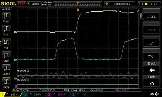
This is how clock (blue) and data (yellow) look on the scope after just ~60 LEDs.

enter image description here

This is after ~1500 LEDs. Purple is the 5V line.
enter image description here

timonsku
  • 1,368
  • 3
  • 14
  • 30
  • Those signals look pretty clean. Is that what it looks like after it starts misbehaving? – Tom Carpenter Jun 10 '16 at 13:15
  • That is at the very beginning. I did some more measurements and updated the post with a clean and a bad signal at the end of the strip. – timonsku Jun 10 '16 at 14:11
  • Is there a single chip after which this starts happening (i.e. is it clean up until after a specific IC) - I wonder if there is a faulty IC in the chain. Although having said that the Data looks fine which makes me wonder whether the clock signal is actually buffered by the IC (hence my answer). – Tom Carpenter Jun 10 '16 at 14:25
  • It's very sporadic which LEDs are affected. They start to flicker in a slight red and later on in the strip they flicker in different colors. If I set these flickering pixels to a color they do show that color but flicker in their "bad" color aswell. – timonsku Jun 10 '16 at 14:35
  • I know that the APA102 has an on board regulator, but is it possible that you still need decouplig capacitors on the VCC/GND connection for each chip? – JRE Jun 10 '16 at 14:54
  • Why do you need such a long string? Is it possible to split the string into 2 or 3 (or more) and have multiple controllers or even use a single MCU with multiple SPI ports. – Gilad Aug 15 '17 at 20:03

4 Answers4

5

Rather than needing line buffers, I suspect that your string is just too long from a power point of view. The strip power and ground traces are simply too thin to carry 30 amps successfully.

I suggest that you find some way to access the power and ground traces (particularly the ground) at 3 meter intervals, and solder a 16 ga wire to each access point. Run the wires back to the power supply. Make sure you insulate the solder joints. At the very least you should be able to access the lines at each end of the strip, which would be better than nothing.

EDIT - With the inclusion of your scope traces, it's pretty clear that you're out of luck. The lower trace indicates that the chip has very slightly slower low-to-high propagation time then high-to-low. This means that, over many successive transmissions a positive pulse (or the positive portion of your clock) will gradually get narrower and narrower. As has happened to you.

But it's not the manufacturer's fault. Look at your numbers. With an 8 MHz clock, it's high for about 60 nsec. Your lower trace shows that your clock pulses have shrunk to almost nothing - call it 10 nsec. This means that you have a propagation delay imbalance of 50 nsec/1500, or 33 psec. Trust me, there's no (single-ended) process which can guarantee better performance.

For what it's worth, a reconnaissance satellite camera had similar problems which were traced to Altera FPGAs which had imbalances of several nsec, and the imbalance was stated in the data sheet. The cure was to invert the clock between each stage so that the imbalances cancelled each other out. Obviously, this isn't an option for you.

As I stated, I'm afraid you're out of luck. The manufacturers apparently never forsaw someone trying to extend their strips to the extent which you're doing.

WhatRoughBeast
  • 59,978
  • 2
  • 37
  • 97
  • Also adding some ceramic bypass capacitance at these junctions couldn't hurt if space/irregularities behind the strip isn't of concern. – user2943160 Jun 10 '16 at 02:38
  • 1
    I feed power into the strip every meter. I would think that this is enough? I'm Using 14 AWG wire. I added a screen of the data and clock signal, they look very skewed alread after just a few LEDs. – timonsku Jun 10 '16 at 11:59
  • @ProfessorSparkles - See edit. – WhatRoughBeast Jun 10 '16 at 16:43
  • Take a look at the timing on the input/output of a single strip and see what's happening. If the clock coming out is at pretty much the same time it went in then you might get away with running the clock around some of them (i.e. using the output clock from strip A to drive the clock inputs strip B, strip C, strip and D). Then use D to drive E F and G or something like that. This will eventually end up with a pulse which is too narrow but might help – Will Jun 10 '16 at 17:27
2

By using "Line drivers" (buffers).

Over a long distance the RC time constant of the traces will be large which in turn acts as a low pass filter killing you signal at higher frequencies. You can solve the problem by reducing either the resistance or capacitance (or both) of the line.

The first option (which works up to a point) is to use a stronger line driver. I've had to drive 32 CMOS inputs over a 1 metre PCB in the past - the load ended up being in the order of 1nF which is highly capacitive. A standard CMOS output won't be able to drive that at much higher than a couple of MHz if you are lucky.

Instead I was able to modify the design to include a MOSFET gate driver to drive the line. These have very strong drive transistors which increases the drive strength (a.k.a reduces resistance) and so can generate a clock signal at a much higher frequency and keep is square enough to work. The trade off is that the peak switching current of that driver is 1A!

The second option (which is much more expandable) is to split the line up in to chunks. If you make the line smaller, it will reduce both the resistance and capacitance of it. So using that principle, if we split the line into smaller chunks and add buffers between each chunk, then each buffer can extend the range of the signal while maintaining a higher clock frequency.

Tom Carpenter
  • 63,168
  • 3
  • 139
  • 196
  • Each APA ic is supposed to buffer the input and shift it by one. How would your solution be different? – Passerby Jun 10 '16 at 00:10
  • @Passerby TBH I didn't look at the APA devices, it just the issue reminds me of similar problems I had in the past. I don't see anything having had a look at the datasheet as to whether the clock is actually buffered, and if it is with what sort of drive strength. – Tom Carpenter Jun 10 '16 at 01:11
1

It is VERY unrealistic to expect to drive 12M of LED strip (1728 RGB LED ICs) from a single point. Either POWER OR DATA.

You must break your 12M of strip into smaller pieces. Not necessarily PHYSICALLY, but ELECTRICALLY. My gut feeling would be that you need to break it up into at least 4 sections and power each section separately. And drive the data separately as well.

Richard Crowley
  • 14,382
  • 2
  • 20
  • 37
0

seems like you could just feed your data and clock from the middle of the strip and outwards towards the two opposing ends. hopefully your controller has two outputs. this should be achievable with a single pixelpusher if not.