I am using BeagleBoard-xM GPIO outputs to drive some DC motors with the help of L293D IC. The problem is that there is a difference between voltage levels. The GPIO outputs only supply 1.8V while L293D needs at least 4.5V for logic high. So I need a unidirectional voltage level shifting. I have BS170 N-channel FETs for this purpose. However I am not good at semiconductors. What is the proper configuration for the transistor? Do I have to use any additional components?
Asked
Active
Viewed 1.9k times
8
-
@curb brought forward a valid point on another answer, what speed signal are we dealing with level shifting, if you are running at 9600 baud it will be much easier then 1GHz. – Kortuk Dec 21 '11 at 15:34
-
@Kortuk Since this is for a DC motor driving circuit, the speed is not so important for me. PWM signal that will drive the circuit is at about 100Hz and I need to set duty cycle between 0 and 100. So theorically 1KHz is enough speed for me. – Emre Yazici Dec 21 '11 at 22:15
3 Answers
15
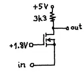
I used following circuit successfully as logic level shifter 1.8 V --> 5V
for frequencies up to some MHz.
The FET I used was a BSN10A.
Curd
- 16,043
- 34
- 43
-
I do not think the OP has that transistor, or has he defined he needs that frequency. This might be a right answer, but can you make a right answer with his component? – Kortuk Dec 21 '11 at 15:35
-
@Kortuk: I guess it works also with a BS170 if he picks a particular device with Vgs(th) that is small enough. – Curd Dec 21 '11 at 17:27
-
Could he use two BS170s, one to step up the voltage to turn on the second fully? – Kortuk Dec 21 '11 at 17:34
-
@Kortuk: no I think that wouldn't work. If Vgs(th) in the first stage is too high a second stage doesn't help. I haven't tested, but maybe raising the 1.8 V to a value that is just high enough (>Vgs(th) but not too high) could help. – Curd Dec 21 '11 at 17:52
-
I am sorry, i have downvoted you. This is specifically because this question uses a different transistor and you are designing for speed when he does not need it and never implied he would. In this circumstance I am not sure the answer is of value. Please do not take this the wrong way, you clearly know your subject matter, but remember the focus is answering the OPs question. I hope to continue getting answers from you. – Kortuk Dec 22 '11 at 03:54
-
@Kortuk: ...this is nonsense. the title of the question is "Level Shifting 1.8V to 5V with N-channel FET". Emre Yazıcı explicitly asked whether he needs other devices than the ones he has. I also explained how he still could use his BS170. BTW: the answer with 2N2222 is much more off topic (other transitor, even not a FET) and has some serious drawbacks. If you think the answer is of no value to Emre Yazıcı you should leave it to him to downvote. – Curd Dec 22 '11 at 10:45
-
the vote will change directions if you can give a schematic using the spec'ed mosfet and a possible solution. – Kortuk Dec 22 '11 at 14:32
-
@Kortuk: He asked for "Level Shifting 1.8V to 5V with N-channel FET" and he got "Level Shifting 1.8V to 5V with N-channel FET". He didn't insist on using a BS170. I don't see what's wrong with the answer. And if he really wants to use his BS170 (if he selects one with a Vgs(th) small enough) the schematic doesn't need change. BTW: both other answers suggest to use other devices than BS170; not even N-channel FETs... – Curd Dec 22 '11 at 21:41
-
I couldn't find any N-channel FET around here that has similar characteristics with BSN10A. I found BSS110 as a small signal FET, however it's P-channel. Can I use a P-channel for the same purpose? If yes what will be the difference in schematic? – Emre Yazici Dec 26 '11 at 17:11
6
The BS170 will not work very well here as it's threshold voltage (i.e when it starts to turn on) is typically 2.1V, which is higher than 1.8V.
So you could use a FET with a lower threshold voltage, but I'd probably just use an NPN for this.
Something like this should do okay:
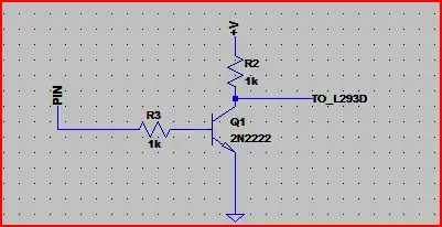
Be aware that the schematic above will invert the logic levels e.t. *0*V@PIN -> +V at the collector.
If you can source a better FET then you can use the above circuit but swap the NPN for the N-Channel FET. In this case the base/gate resistor is not necessary, but it won't do any harm providing you don't need to switch at very high speeds (this particular solution is for lowish speeds)
Resistor values are not too critical, the R3 is to limit current flow into the base of the transistor, and R2 sets the current through the transistor.
If we assume the gain of the transistor is ~100, then if you wanted to reduce current drawn from the pin (e.g. battery powered device that needs to be power conscious) you could go a lot higher than 1k with R3 (probably up to around a maximum of 15k), as the base needs a minimum of only 5mA / 100 = 50uA to work (the 5mA comes from 5V / 1k (R2) )
If higher speed switching is needed you are probably best off with a level shift IC. Here is a Maxim page that mentions a few high speed level shift ICs.
Oli Glaser
- 54,990
- 3
- 76
- 147
-
Thanks for your valuable suggestions and the schematic. Minimum gate threshold voltage for BS170 is 0.8V, so isn't that possible to switch it on with 1.8V? What is difference between min., max., and typical values of Vgs? – Emre Yazici Dec 21 '11 at 12:24
-
1This will not work, however, for fast signals (> ca. 500kHz) because the transistor will turn off too slow. See my answer to http://electronics.stackexchange.com/questions/23349/what-is-wrong-here-a-simple-npn-switch – Curd Dec 21 '11 at 15:18
-
@Emre Yazıcı: min, typ., and max means that if you have a large number of transistors of that type all possible values are in the range between min. and max. value. The typ. value is most likely one. – Curd Dec 21 '11 at 17:31
-
@Curd - No, I was assuming low speed here. If high speed is needed then a dedicated level shift IC might be a better idea. Places like Maxim,TI,etc make some decent ones. – Oli Glaser Dec 21 '11 at 18:33
-
I have implemented the circuit that is shown on the diagram. Without L293D Vr3=1.14V, Vbe=0.7V and Vce=5.54V (Power supply is 5.5V). However when I connect L293D's enable pin to the collector, Vce and Vr2 become 2.77V. Unfortunately this voltage is not enough to enable L293D. By the way, I made power supply's and the microcontroller's ground common, connected to emitter of 2N2222. Is there anything that I am missing? – Emre Yazici Dec 25 '11 at 20:33
-
@EmreYazıcı - Something seems out there - if your GPIO pin is at 1.8V, then Vce should be <0.2V, not 5.54V. The circuit is *inverting*, so for 5.5V at the collector you need 0V at the GPIO pin. – Oli Glaser Dec 26 '11 at 06:59
-
1
I'd vote for a bus switch. It's like using the circuit in Curd's answer, but with small MOSFETs optimized for this purpose (low Vds breakdown, low parasitic capacitance, low gate resistance).
We've used Fairchild NC7SZ384 for this purpose; other manufacturers make them also.
Jason S
- 13,950
- 3
- 41
- 68