If you put the 5V and 12V in parallel, the voltage would be somewhere in between depending on the internal resistance of each source.
If both sources have equal internal resistance then the resultant voltage would be 8.5V.
This would apply for e.g. batteries or similar simple voltage source.
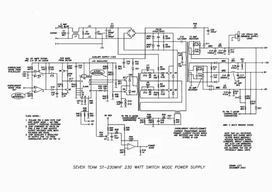
With two switching supplies though, as W5V0 has noted, the resultant voltage will likely be the higher of the two, as the lower rail cannot sink current (due to the diode) and will effectively look high impedance to the 12V rail. So all that should happen (see below) is the lower rail will rise to the potential of the higher rail.
It is not a good idea to connect two different supply rails directly due to the problems that can be caused by low impedance sources opposing each other and circuitry of the lower rail may not rated to handle the voltage from the higher rail.
However in the switchers case it's probable no magic smoke will appear due to the inability to sink current mentioned above. However it's possible that the lower rails diode won't like being reverse biased so much and any capacitors may not be rated for the higher voltage (definitely a possibility given the extremely competitive price these things aim for - every cent makes a difference)
If a mid point voltage source is needed then a regulator of some sort can be used to provide a low impedance source.
The link you provide is for connecting batteries of the same voltage, which can be regarded as completely separate sources. The rails in your PSU will share a common ground (like two batteries with their negative terminals connected together) If you try and connect them in series it will effectively short one of the rails to ground which is not good.
It's not too clear what you are trying to do with the outputs without a schematic or some more info as to what voltages and control system (e.g. protection, voltage/current adjust, etc) you want to end up with.
For the minimum load on each rail you just need to use two separate resistors to ground.

