I have been learning about the 7489 memory chip. I had two of these that turned out to be broken (see here for previous question on this). I got more and I have finally gotten everything to work.
From this answer, I learned the basic idea of how to set up the circuit. So now I have the following (schematics more or less copied from here). The following works well!
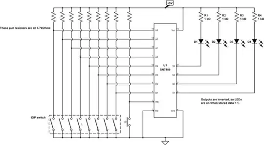
simulate this circuit – Schematic created using CircuitLab
I am still new to digital electronics and I am just trying to learn. My question is: How can one determine an appropriate pull-up resistor?
For example, in the answer to the earlier question, the resistors R1, R2, R3, and R4, were suggested to be 2.2 kOhms. I chose 1kOhm. Does it matter? Is all that matters what the LEDs need or is there something relating to the 7489 that helps determine the size of the pull-up resistors? If it is only the LEDs (forward voltage 2V and current 0.20 mA) I would guess that I could actually use 220 Ohm. Is that right?
Also, for the inputs (address and data input) I did choose 4.7 kOhm. What here determines the size? There are no LEDs so I assume it has to do with the IC, is that correct? What should I be looking for in the datasheet?