In an attempt to idiot proof a device I am designing that needs both 24V DC and 120V AC inputs for logic, I set out to create an input system that could handle either voltage going to a simple 3.3V micro controller. Below is the schematic of what I came up with. Simulation shows that using a Depletion mode FET combined with a sensing resistor, I should be able to limit the input current regardless of the input voltage. This with an opto-isolator and rectifier before hand should effectively allow me to sense 24 and 120 volts interchangeably.
I'm new to depletion mode Mosfets and did not see much about this type of application other then an app note from Infineon here.
Below is the basic circuit I am describing, the 180V input can be exchanged with a 24V dc input. this is basically the input pin to the system.
Edit:
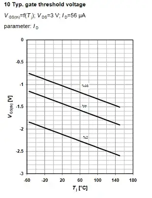
The simulation only has -0.6V Vgs to limit the current, that does not match the expected -2.1 - -1.0 in the datasheet, but that is for a mere 56uA. Turns out that the data sheet later on lists the variation of Vgs and my model falls within that range.
The one issue I found in the data sheet so far with this plan is that it appears that N-Mos Depletion Fets suffer from thermal runaway when used in this fashion... At least that is what I gather from the image below.
Can anyone give me any advice on if this is a good path to take?

