13

Background: I'm using an L293D dual H-Bridge to drive a DC motor, but only one motor, and the package contains two complete H-Bridges. This is all being soldered onto Veroboard (stripboard).

Question: Is it possible to use the two sides of the chip sort of "dual wired" in parallel? Arguably to supply more current (not strictly necessary) but really so I don't have to cut as many strips on the stripboard.

Here's my reasoning... Apart from Vin and 'enable', the two sides of the chip are mirror images, in other words, it seems to me that I could leave the stripboard intact across the chip for The inputs, outputs and ground pins. I would use output 1 and 4 together for one terminal of my motor, and Output 2 and 3 for the other. I'd then also have Input 1 joined to 4 and Input 2 joined to 3. (The input signals are coming from a Netduino)

I was already planning on having all the GND connected, as they're also used by the chip for heat sinking.

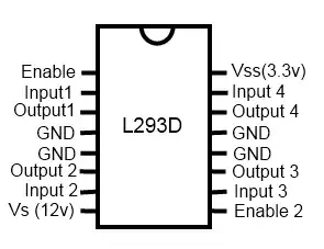
Here's a badly drawn pinout of the chip.

L293D pinout (badly drawn)

Edit: Datasheet here: http://oomlout.com/L293/IC-L293D-DATA.pdf

2nd Edit: Having read the datasheet in reference to Olin's answer I Can't find any reference to whether they use FETs or not, (in fact the word "transistor" only appears once in reference to a possible load). I have found reference to people stacking or Piggybacking these chips on top of one another (to provide more current). If that's possible then I'm guessing wiring across should work. I will give it a try and report back.

Andrew M
  • 377
  • 2
  • 4
  • 12
  • It didn't occur to you to provide link to the datasheet!? – Olin Lathrop Dec 14 '11 at 20:18
  • It did, :) but I wanted the picture in the question, I was going to copy-paste it but fretted about copyright. Only took 3 mins to knock up a new one. – Andrew M Dec 14 '11 at 20:20
  • There is a lot of other information in the datasheet beyond just that picture. – Olin Lathrop Dec 14 '11 at 20:21
  • Sorry yes, I've just read your answer, I've added a link, and I'm reading the datasheet now. – Andrew M Dec 14 '11 at 20:28
  • 1
    As I said in my answer, if you're not going to exceed the current rating of a single H bridge, then you don't have to worry about current sharing between the two when you tie them together. – Olin Lathrop Dec 15 '11 at 00:17

3 Answers3

9

Yes, you can definitely parallel the two outputs of an L293D. I made a few stepper drivers based on L293D with parallel outputs and had no problems.

As this application note from ST Microelectronics (APPLICATIONS OF MONOLITHIC BRIDGE DRIVERS) states:

Higher output currents can be obtained by paralleling the outputs of both bridges. For example, the outputs of an L298N can be connected in parallel to make a single 3.5 A bridge. To ensure that the current is fairly divided between the bridges they must be connected as shown in figure 2. In other words, channel one should be paralleled with channel four and channel two paralleled with channel three. Apart from this rule the connection is very straightforward - the inputs, enables, outputs and emitters are simply connected together. The outputs of an L293 or L293E can also be paralleled - in this case too, channel 1 must be paralleled with channel 4 and channel 2 with channel 3.

enter image description here

But you should be aware that the total current capability of the parallel outputs would be less than the sum of the two channels (< 1200 mA).

EDIT: The only differences between the L293/L293E and the L293D are that:

  • the L239D has internal clamp diodes included

  • the L293/L293E has higher output current capabilities.

m.Alin
  • 10,638
  • 19
  • 62
  • 89
  • 3
    Awesome - Thanks. This is what I did in the end, and it worked fine for me too, but it's nice to get it confimed. – Andrew M Jan 15 '12 at 16:52
  • @m.Alin I know this post was made a few years ago, but I am trying to do the same thing with a stepper. You mentioned you did this, could you post a schematic to it? Also, did you use a breadboard or did you piggyback it (for thermal transfer between the chips)? – electricviolin Jul 28 '15 at 15:28
  • @electricviolin Well, the schematic is already posted above. But you might have misunderstood. I haven't used two different L239D ICs; An L239D has two integrated H-bridges and I paralleled those two together. – m.Alin Jul 28 '15 at 16:39
  • Oh. I had an idea - could I use two different l239D and connect one to each coil of the stepper (essentially treating one stepper as two different motors). I would use the schematic you posted to put the chip in parallel with itself to it could handle a higher current. This is a bipolar stepper by the way. – electricviolin Jul 28 '15 at 16:53
  • @electricviolin I believe you'll be better off searching for a more powerful H-Bridge driver.. – m.Alin Aug 05 '15 at 08:20
  • @m.Alin Yeah - I was looking at the l298, which is rated for 4 amps. It is quite pricey though... are there any alternatives you would reccomend? – electricviolin Aug 05 '15 at 15:44
  • @electricviolin I don't know about price, but the L298 are quite old & inefficient; it drops a lot of voltage at high currents. I'd suggest you look the the [DRV8x series from TI](http://www.ti.com/lsds/ti/apps/motor/products/integrated_motor_drivers.page). They look promising. – m.Alin Aug 05 '15 at 15:53
3

You'd have to look in the datasheet and see how exactly the H bridges are implemented. If they are implemented with FETs, then they should be able to load share reasonably well. The other thing to watch out for is the exact break before make behaviour. Check the absolute timing, not just the relative timing within one H bridge. Chances are that's fine though.

If you don't plan to exceed the current rating of one H bridge, then even load sharing is not a issue. So the answer is most likely it's OK, but of course without checking the datasheet this is just a guess.

Olin Lathrop
  • 310,974
  • 36
  • 428
  • 915
1

If you look at the datasheet on p. 3, some of the specs are VCE(sat) -- the C and E stand for collector and emitter of PNP/NPN (bipolar) transistors, which don't current share directly: if two NPN or PNP transistors are hooked up with all 3 terminals in parallel, when one gets hotter than the other, its VCE decreases, causing it to shoulder more of the current, which causes it to heat up more, and you get a positive feedback effect.

However, the internal circuit may have been designed to allow paralleling H-bridges -- but it doesn't seem to say anything about this though.

Jason S
  • 13,950
  • 3
  • 41
  • 68