This can be easily accomplished with a pulldown resistor. That's a fancy name for a resistor to ground. The resistor value is set low enough so that the line is held solidly in the logic low state when nothing else is driving it. The value is high enough to not exceed the current source capability of anything that needs to drive the line high.
For example, let's say the line can be driven by a CMOS logic output that can source up to 4 mA in the high state. At 3.3 V, it takes (3.3 V)/(4 mA) = 825 Ω to draw 4 mA. That's the lowest allowed pulldown resistance. You could safely use 1 kΩ, for example.
There are more tradeoffs, so see this explanation of pullup resistors. Pullups are the same concept, except the line is held high when not driven instead of low.
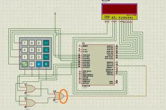
Added in response to schematic
You are asking about a line that is either left high-z or actively driven high. However, that is very unlikely what is actually happening here. You show this line being driven by a OR gate. Those usually either drive actively in both directions, or sometimes drive actively low with high-z for the other state. Check the datasheet.
Asking for a "truth table" for this makes no sense.
These two confusions indicate that you have too many basic misconceptions and too little basic knowledge for a reasonable answer here to be possible. The best I can suggest is to give this project to someone that knows what they are doing. Perhaps you can learn a little from them.
