I need to drive a ratiometric current sensor ACS758xCB with a nominal supply current of 10 mA. Due to the ratiometric nature of the sensor I would prefer to supply it from the reference voltage of my ADC. Obviously I need to buffer the reference.
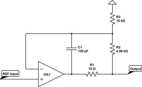
However, most op amps, notably those with low offset voltage, require the capacitive loading of the op amp be limited. Since the sensor itself contains active circuitry it requires supply bypassing in the range of 100 nF.
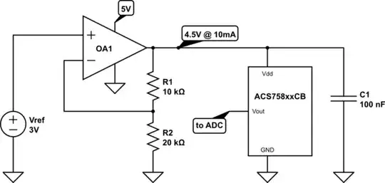
simulate this circuit – Schematic created using CircuitLab
How does one usually cope with this situation? I've looked into tracking regulators such as TPS7B4250 but the tracking performance of +/-5 mV does not sound too impressive.