5

I have a keyboard from an old Silent 700 TTY that I'm trying to bring to life. The problem is that each individual keyswitch appears to be a hall effect sensor. There are no part numbers; the chip dies are individually bonded to the carrier boards.

Here's the switch. The carrier board fits into a slot in the back of the switch in the orientation shown:
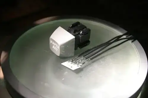
Image of the switch

And here's the die:

Image of the die

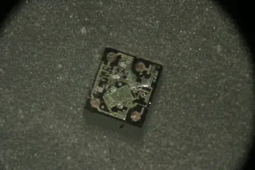
Does anyone have any thoughts on how to drive a switch like this?

phooky
  • 1,008
  • 7
  • 12
  • Could you please clarify: 1. Are the keys broken and you want to fix them. 2. Do you want to use them in some other project. 3. Do you have a working keyboard? – jpc Apr 23 '10 at 19:08
  • The keys all still work, to the best of my knowledge. The full keyboard is a subassembly of a fried Silent 700, and is connected by a pin header with about forty contacts. I'm trying to convert this to a USB keyboard. We used to have a working Silent 700 as well, but it was donated to another hackerspace some time ago. – phooky Apr 24 '10 at 02:35
  • Giving away Hall effect keyboards is stupid. They're the most reliable and durable keys that exist. – stevenvh Jul 19 '11 at 07:13
  • @stevenvh: also the most expensive. Apart from the [Optimus Maximus Keyboard](http://www.artlebedev.com/everything/optimus/) maybe – Federico Russo Jul 19 '11 at 07:19

1 Answers1

3

Analog hall sensors are 4-pin so maybe this is one? If this is the case then you should drive constant current through one pair of contacts and measure the voltage on the other (I think they are unfortunately not interchangeable so you would have to guess).

On the other hand the die layout looks a little complicated for a simple analog hall sensor.

jpc
  • 5,302
  • 1
  • 24
  • 45