0

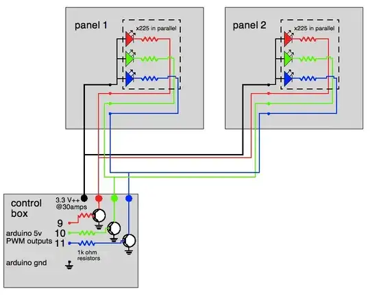
Why doesn't this work? I have fifteen RGB LEDs wired up with this configuration. The transistor I'm using is the MJE3055T. Are the transistor's voltage ratings (collector-base, collector-emitter) just too high for this low-voltage, high current application? When I eliminate the arduino and transistor and plug the LEDs directly into the power supply (with resistors of course) they work perfectly...

Does anyone know why this isn't working? Have suggestions for a different transistor?

Thanks!

led schematic

  • 1
    Do they not turn on, or not turn off? – Chris Stratton Dec 10 '11 at 20:25
  • 1
    Do you know that your code is working okay? Have you tried hooking the output of one of your transistors to single LED and resistor? – tcrosley Dec 10 '11 at 21:01
  • Also, please post a link for the datasheet for the RGB LED. – tcrosley Dec 10 '11 at 23:07
  • You have now clarified that each panel holds a single RGB LED, and that the current per LED per color is 20mA. So what the heck is the "x225 in parallel" supposed to mean?? – Olin Lathrop Dec 12 '11 at 18:21
  • "x225 in parallel" means 225 RGB leds in parallel. I'm going to have two panels with 225 LEDs each (450 total). I've only hooked up 15 so far. Actually - I just got them to work, Apparently the arduino pin I was working with initially got blown out a while ago. I'm using Max/MSP in conjunction with the MC to control the brightness of the LEDs. Why would a FET be more effective than a bipolar transistor in this application? – whataniceguitar Dec 12 '11 at 18:55
  • 1
    A FET (usuallu MOSFET) is voltage controlled and draws essentially no current when on or off. It draws current durung switching only to chah and discharge the gate capacitance which is a few NF at most. So a MOSFET is easily controlled directly by a mirocontroller oun (provided he voltgae is high enough for yhe FET used). | A Transistor is current controlled where I base = Iload / Beta, where Beta is the current gain of the transistor. Large power tansistors tend to have lowish Betas. Yours has aguaranteed Beta of 20 so to switch 10 Amps you'd need 0.5A base drive. – Russell McMahon Dec 12 '11 at 19:01

2 Answers2

3

Do the math on the currents. That transistor only has a gain of 20 that you can count on. With 1 kΩ base resistors to 5V, the base current will be about 4.3 mA. That times 20 is only 86 mA. That will be shared by all the LEDs that the transistor is driving. Since you say there are 15 LEDs in parallel, that means each only gets 5.7 mA, which will be visible but dim.

What current do you want to run each LED at? That times 15 is the current the transistor needs to be able to sink. That divided by the transistor's gain is the minimum base current required.

There are several solutions that come to mind:

  1. Use a transistor with more gain.

  2. Give it more base current. The limit is what the arduino can supply. You'll have to check the arduino datasheet for that. Probably in the 10-20 mA range, but I haven't checked.

  3. Use a FET instead. This is actually a good application for a FET. I like the IRLML2502 for low side swithing from 5V logic. In this case you drive the gate of the FET directly from the microcontroller digital output without a resistor in series.

It would help if you said what the max current per LED is intended to be.
Olin Lathrop
  • 310,974
  • 36
  • 428
  • 915
  • According to Figure 1 of the datasheet for the transistor, the typical hFE is between 50 and 100 for collector current under a couple of amps, and the min hFE of 20 is at 10A. I know that typical is no guarantee, but I wouldn't expect all three transistors to be that marginal. The outputs on the ATmedga168 used on most Arduino boards appear to be able to source up to 40 ma (I've never used one, just reading the datasheet). Using a smaller base resistor or a FET are good suggestions though. – tcrosley Dec 10 '11 at 22:30
  • @tcrosley: The OP *still* hasn't answered the important question of how much current each LED is supposed to get, so we can't really say. However, let's pick 20mA. That times 15 LEDs is 300mA total. The base current is about 4.3mA. 300mA/4.3mA = 70, which is the minimum gain the transistor would need to have. That transistor could be well below that and be perfectly within spec. – Olin Lathrop Dec 11 '11 at 14:11
  • I agree with your analysis, that the circuit is marginal, and believe a smaller base resistor, say 470 or 330 ohms, would be a quick fix. But most LEDs work pretty well at 10 ma. My concern, as yours, is that we don't have the full specs for the LEDs. He is running them at 3.3v with a 225 ohm resistor, which isn't going to leave much voltage across each LED. It's impossible for each one to draw 20 ma, since that would imply a 4.5v drop across the resistor. – tcrosley Dec 11 '11 at 15:47
  • @tcrosley: Good point about the 225 Ohm resistors. I have no idea what the "x225" is supposed to mean, so I ignored it. If that is indeed the value of each resistor, then the current thru each LED must be quite low. – Olin Lathrop Dec 11 '11 at 16:24
  • The outlined area indicates a single RGB LED, I'm sorry about not being more clear about that. for the red channel, i'm using a 5.6 ohm, and for blue and green i'm using 68 ohm resistors. The RGB led is rated (respectively) at 2.0v, 3.2, and 3.2, all at 20ma. – whataniceguitar Dec 12 '11 at 18:10
  • @whata: In that case what I said in my answer applies since the total current for each color will be 300mA. – Olin Lathrop Dec 12 '11 at 18:19
1

How many LEDS are there?
You say 15 BUT is that

3 x 5 or
3 x 15 or
... .

And what does "X225 in parallel" mean?
225 LESDs,
450 LEDs,
...?)

As you say 3.3V at 30 Amps it sounds like you may be intending to drive 10A per transistor (!).
USE A MOSFET!!!
Olin's IRLM2502B would lose its chest hairs at that current.

If all 10A are switched in one MOSFET then choose a suitable MOSFET from eg Digikey's nice selector guide.

eg IPB114N03L (Infineon) Under $1 at Digikey in 1's and in stock 30A, 30V. About 0.1A V drop at 10A at 5V drive.
This is TO220.
TO263-3 also available.

Russell McMahon
  • 147,325
  • 18
  • 210
  • 386
  • The IRLML2502 is applicable if there are fifteen LEDs being driven as the OP said. If the "x225" means there are 225 RGB LEDs on each panel all driven together, then I totally agree the IRLML2502 is insufficient. If each panel really has that many LEDs, I would put a driver or perhaps several on each panel. – Olin Lathrop Dec 12 '11 at 13:33