6

I read in 'The Art of Electronics':

Power factor is a serious matter in large-scale electrical power distribution, because reactive currents don't result in useful power being delivered to the load, but cost the power company plenty in terms of I2R heating in the resistance of generators, transformers, and wiring.

However, I have also read many times that only 'True Power' is dissipated.

How do reactive currents cause I2R heating?

Dave Tweed
  • 168,369
  • 17
  • 228
  • 393
STATER
  • 63
  • 4

5 Answers5

7

The power dissipated in the wires is not reactive power, because the voltage drop in the wires is in-phase with the current through them. This is real power.

If the load is purely reactive (a pure inductance or pure capacitance), the voltage across the load is 90° out-of-phase with the current, and so no real power is dissipated there.

Therefore, the load seen by the generator has both a real component and a reactive component, because the current draw that it experiences has a phase relationsip that falls somewhere between 0° and 90°.

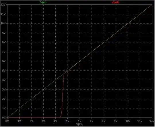
Another way of saying this is that the voltage at the load is not in-phase with the voltage at the generator, because of the resistance of the wires. Here's a diagram to illustrate the point:
enter image description here

The generator, the load and the wires are all in series, so there's only one value of current that applies at all points in the circuit. KVL tells us that the voltages must sum to zero; another way of saying this is that the generator voltage must match the sum of the load voltage and the wire voltage.

If the load is a pure reactance, the voltage across it is 90° out of phase with the current. However, if the wire is a pure resistance, then the voltage across it must be in-phase with the current. Therefore, we must add these two values as complex numbers, which means that the magnitude of the generator voltage must be equal to the length of the hypotenuse formed by the two voltages, or the square root of the sum of their squares.

As you can see from the diagram, this means that the current is NOT 90° out of phase with the generator voltage — and the in-phase component represents the power dissipated in the wire.

Dave Tweed
  • 168,369
  • 17
  • 228
  • 393
  • I know that you know this stuff, so I suspect that you're not saying what you mean to say with ... "Another way of saying this is that the voltage at the load is not in-phase with the voltage at the generator, because of the resistance of the wires." – placeholder May 16 '16 at 13:30
  • 2
    @placeholder: No, that's exactly what I mean to say. Set up a simulation, or draw the phasor diagram -- in any case, the voltage at the load does not have the same phase as the voltage at the generator. The magnitude of the difference depends on the relative values of the resistive (wire) and reactive (load) impedances. – Dave Tweed May 16 '16 at 14:54
  • That sentence says directly that the phase difference is due to resistance. It clearly cannot be unless you have reinvented complex math. The amplitude yes, the phase no. Orthogonality matters. – placeholder May 16 '16 at 14:58
  • @placeholder: I don't understand the point you're trying to make. If the wires had no resistance, there would be no phase difference. It's a simple R-C or R-L circuit. – Dave Tweed May 16 '16 at 15:03
  • Most excellent edit! – placeholder May 16 '16 at 19:18
  • I think this answer is correct but, in the context of power systems given in the question, may be a bit confusing. For example, transmission lines are not simple wires; inductance dominates rather than resistance. So "the voltage drop in the wires is in-phase with the current through them" wouldn't be the case for a realistic power system. Also regarding "voltage at the load is not in-phase with the voltage at the generator, _because of the resistance of the wires_" - usually it would be deemed that the reactance in the circuit was the "cause" of the phase shift, rather than the resistance. – sblair May 16 '16 at 22:56
  • @sblair: Yes, real-life power distribution systems are electrically much more complicated than what's being discussed here. However, this question is focusing on the specific issue of how the resistance of the wires leads to real power dissipation even with a purely-reactive load. – Dave Tweed May 17 '16 at 12:17
  • @DaveTweed Regarding reactive power of an LR circuit or an induction motor: If the energy stored in magnetic filed leaks somehow, can we still say that reactive energy circulating back and forth between the source and the load has no effect on system's energy loss? Do we assume there is no magnetic filed energy loss when we talk about reactive power. – user16307 May 23 '16 at 01:54
4

Because the power line wire has the resistance, so reactive current I that goes back and forth on the power line causes heat on power line I^2*R.

placeholder
  • 29,982
  • 10
  • 63
  • 110
Marko Buršič
  • 23,562
  • 2
  • 20
  • 33
  • [`"First, the reactive power is not dissipated"`](http://physics.stackexchange.com/questions/134874/why-doesnt-a-resistor-dissipate-reactive-power) Am I misunderstanding something? – STATER May 16 '16 at 10:23
  • 3
    Don't know why this was downvoted - it is essentially correct (though short enough it should have been a comment). Reactive current (a) causes real dissipation in cables, transformers, etc and (b) requires all components to be uprated to carry it (or reduces the real power that can be delivered over an existing circuit. –  May 16 '16 at 10:24
  • @STATER Did I said that reactive power is dissipated? – Marko Buršič May 16 '16 at 10:45
4

It might help to investigate what I^2*R heating is.

From Ohm's Law, V = I * R, so
P = V * I
P = (I * R) * I.

Note that I is by definition in phase with itself, so whether or not I is reactive, is irrelevant when considering I^2*R losses in cables and transformers. Whatever the phase of I, I^2*R is real power.

This is in contrast to the useful power dissipated in the load, which is V(supply) * I and there is no inherent relationship in the phase between them, hence only the real component of I matters.

4

Any current delivered to a load causes power losses in the cables between supply and load and, a load with poor power factor, requires more current for a given wattage in the load hence, there are greater power losses in the cable infra structure. This is a cost that the supplier has to bear.

Andy aka
  • 434,556
  • 28
  • 351
  • 777
0

Purely reactive impedances don't dissipate real power. Short wires typical in house or appliance wiring have a large non-reactive component of impedance, and dissipate well. That's all there's to it.

The confusion stems from the fact that the voltage across the reactive load is not the voltage across the resistive wire, and that it is the charasteristics of the circuit element that determine dissipation. And wires are circuit elements just like everything else.

The voltage developed across pure resistance is proportional to the current. The voltage is in-phase with the current. There is no other "voltage" that would be "out of phase". That only exists across the load, across the generator, and across the reactive part of the wire/transmission line's impedance. Power transmission lines are more inductive than resistive, but that's not the case for wiring orders of magnitude shorter.

schematic

simulate this circuit – Schematic created using CircuitLab

In the circuit above, the current through all the elements is identical, since they are all a part of a single current loop:

Current waveform in the circuit

The voltage developed across the resistors is in phase with the current. The voltage across the inductor is out of phase with the current.

Voltage waveform across the resistors and the inductor

Note how the phase of the voltage differs between the source and the load. That has to be the case, since the phase of the voltage dropped across the wires is different than the phase of the voltage developed across the source

The average real power developed across the resistors is non-zero - it's a squared sine, with a non-zero mean. The real power developed across the coil averages to zero - it's a sine with zero mean.

The power waveform developed on the resistors and the inductor