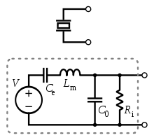
Is there any description anywhere of how voltage, current, mass, momentum, and air interact in a typical audio piezo, and what sort of signal should be expected on the third pin of a three-terminal device (phase relationship with regard to drive, etc.) I'd like to drive a piezo as loudly and as efficiently as possible from a small battery; presumably that would imply trying to maximally exploit its resonant behavior. The normal circuit given for driving 3-wire piezos looks inefficient to my eye (similar to a class A amplifier), though perhaps there's something about the way piezos behave electrically which would cause the resistors to spend most of their time sitting with very low voltage across them.
I've google searched for audio piezo electrical behavior, and didn't find anything useful; I did find some explanation of how crystals work, but I would think the diaphragm coupling piezo-element vibrations to the air would substantially affect the behavior.
Addendum
I understand pretty well how motors work: an ideal motor can be modeled as a black box such that the voltage across the motor leads at any given time will be some constant number of volts per (revolution per second), and the current through the motor will be some constant number of amps per ounce inch of applied torque, and most practical motors can be modeled as an ideal motor in series with a resistor and inductor. What I'd like would be a similar understanding for piezos.
The voltage across a piezo doesn't seem to represent its absolute position, nor its velocity, nor acceleration. What would the voltage on an "ideal" piezo represent, and what must be added to the model of an ideal piezo to make it reasonably match real-world behavior?
