Suppose I have a simple practical inductor as such:
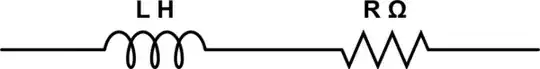
simulate this circuit – Schematic created using CircuitLab
L is known. R is unknown and we need to find it. The supply frequency (say \$f\$) is known. Also the reactive power on the whole inductor (say \$Q_i\$) is known.
Here's my approach. The reactance on the inductive part would be (say \$\chi\$ )
$$\chi = \omega L$$
(where \$ \omega = 2*\pi*f\$). So the impedance triangle and the power triangle would be something like this:

that angle a is equivalent in both triangles. so this would mean that:
$$\frac{\chi}{R} = \frac{Q_i}{P_i}$$
We don't have \$P_i\$ ...however I have a source that says that the equation is just
$$\frac{\chi}{R} = Q_i$$
and that we can get R. The source doesn't provide steps. Just the equation. What am I doing wrong??
Actually I need to solve (the first part) of a question. Here's a screenshot of the question and the part of the solution of concern.

