4

I assume this question is very common, because I read a lot of answers here, but I still missing somthing..

I have "Electric Imp" module, which have max I/O pin power output of 4mA, and its run on 3.3V.
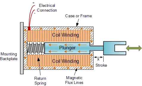
I need to run electric door, which consume 12vdc 500mA at max.

So i started and checked the 2N2222A transitor:
Ic(MAX) = 1A - good enough.
Vceo(MAX) = 40V - good enough

and now I am geting to the base needs (the gain):
in the Hfe I see that the closest is Ic=500mA, Vce = 10V (I need 500mA and 12V, so it is close enough), the gain for this will be 40, which means I need 500/40 = 12.5mA as output.. I do not have it.. am I right so far?

Another thing I am missing is - where can I see in the datasheet that 3.3V is enough on the base, BJTs is not Voltage , but current base, right?

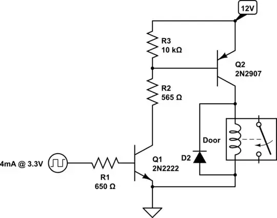
if I am right so far, so I need 500mA/4mA = Hfe of 125, but I couldnt find such resistor.. I can add relay 12vdc coil with lower current than 500mA and use the NPN to run the coil so it will run the door lock..

Thanks, Gabi.

gabi
  • 343
  • 2
  • 5
  • 17
  • 1
    I am confused regarding you question, but possibly use a darlington pair transistor if the hfe of one is too small. For example BD681 has a hfe of 750. – Marko Buršič May 09 '16 at 16:53
  • Why don't you use a mosfet, like this: https://www.embeddedrelated.com/showarticle/77.php ? (Some caveats are exposed here: http://electronics.stackexchange.com/questions/13075/is-it-safe-to-drive-a-mosfet-from-an-output-pin-of-a-microcontroller ) – Sredni Vashtar May 09 '16 at 18:13

2 Answers2

8

You are correct. With a gain of 40, the 2n2222A is not right for your limited current. There are four solutions.

  1. Replace the load with something smaller. Using a smaller relay, which turns on the electric door lock.

schematic

simulate this circuit – Schematic created using CircuitLab

  1. Make a Darlington Pair with two transistors. The beta will square, but the voltage drop across the base will be higher (1.4V instead of 0.7V). Just need to recalculate the resistor.

schematic

simulate this circuit

  1. Use the 2n2222 as a switch for a PNP transistor. A 2N2907 is the typical complementary PNP transistor for the 2N2222, but any suitable PN will work. R3 is a weak pull up, R2 sets the base current for Q2 when Q1 is on.

schematic

simulate this circuit

  1. Use two NPN as a simple switch. This inverts logic. When your output is low, Q1 is Off, so Q2 is on via R2. When your output is high, then Q1 is On, pulling Q2's base to ground, keeping it off. The default state of this, when the GPIO is not yet turned on, may result in the lock opening when the GPIO is not yet turned on.

schematic

simulate this circuit

Passerby
  • 72,580
  • 7
  • 90
  • 202
1

schematic

simulate this circuit – Schematic created using CircuitLab

Something similar like that.

Marko Buršič
  • 23,562
  • 2
  • 20
  • 33
  • Wow, very cool, I did not knew BC517 derlington pair. in its spec I see the gain is 1000 (figure 2), and looking at the graph I see voltage drop of 1v, at 500mA Ic. so if i need 500mA and the gain is 1000, I need to give the base 0.5mA , lets say 1mA. if my output voltage is 3.3, and I need the base to get 1V for saturation, i need the resistor to get 2V. R=V/I=2/0.001=2000 ohm. Why did you wrote 0.18mA and 10Kohm on the base? (I see why the R=10Kohm if I-0.18mA, but in the spec I see gain of 1000, not 30000).. – gabi May 09 '16 at 17:48
  • 1
    @gabi I have this one: https://www.fairchildsemi.com/datasheets/BC/BC517.pdf, while I was cheating the schematics with this one: http://www.ebay.com/itm/16-SPDT-Power-Relay-Module-OMRON-Relay-24V-Coil-10A-277VAC-30VDC-/400343423968 – Marko Buršič May 09 '16 at 18:29
  • I understood it, but i just need to understand the gain, you wrote it is 30000, but on figure 2 on the datasheet i see b=1000 – gabi May 09 '16 at 18:35
  • Vbe(on)=1.4V; 3.3V-1.4V=1.9V, R=V/I=1.9V/0.18mA=cca 10kOhm; 0.18*30000=5400mA (saturated). I don't know why they put 100k resistor. Maybe you want something more powerful and you can choose some BD transistor or TIP122,...the BC517 is so tiny. – Marko Buršič May 09 '16 at 18:37
  • 1
    @gabi Sorry, I can't explain the real hfe of this transitor, I see the beta of 1000, too. It was just an example, I would choose different one for door lock, a power transitor this is too small in my opinion. If you have two 2n2222 you can use the suggestion of Passerby. – Marko Buršič May 09 '16 at 18:43