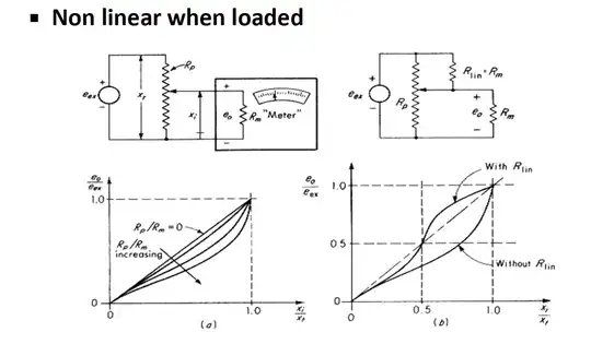
I could not understand why is adding 'Rlin' in the second figure improves the linearity of the system? A little help pls!
1 Answers
The highest output resistance of the pot connected as a voltage divider is at mid-rotation and it is obviously Rpot/4, since the resistance of the two halves is in parallel to stiff voltage sources.
By connecting a resistor equal to the load to the opposite rail you can reduce the nominal error at mid-rotation to zero. You are still left with the 'S'-shaped residual error that is maximum around 1/4 and 3/4 rotation.
That's the hand-waving explanation that should be intuitively useful, but if you want to get real numbers, you can run the rather simple math through Scilab, Excel, a C program, or whatever.
This being Q2 2016 (as of this writing), in many cases it's just as easy to throw an op-amp buffer at the problem and then the loading becomes just the bias current of the op-amp. There may be other problems (the op-amp may not be able to work right to the rails, for example, or the offset drift of the op-amp may be much worse than the pot) but nonlinearity due to loading is pretty much eliminated.
- 376,485
- 21
- 320
- 842
-
Why is there an error only after we load the potentiometer? before loading it is ideally linear right? Does it have something to do with the current that is being drawn by the added load? @Spehro Pefhany – Hilton Khadka Apr 30 '16 at 14:23
-
Yes, it's ideally linear. Why it is nonlinear with a load is answered in your [other question](http://electronics.stackexchange.com/questions/231488/electrically-loaded-resistive-potentiometer/231515#231515), both by Andy and myself. – Spehro Pefhany Apr 30 '16 at 15:37
