-1

If a resistor is suppose to resist over current to the load through a cable in a series DC circuit then why would you ever place a resistor on the positive cable side instead of the negative cable side. I mean that's where all the electric current with it's electric energy (negatively charged electrons) is coming out of to power the load with electric energy to DO WORK, and in this case too much of it before reaching the load and destroying the load. If the electrons with their electric energy charge were coming out of the positive side I would understand, but they don't...or do they.

-the question is in the title.

Edit: I don't want to know if or how the electrons KNOW what to do at the resistor. I want to know why would you put a resistor on the cable that's on the positive red side of the battery that doesn't supply any electrical energy/voltage/force to the load it just accepts electrons back into the battery.

Max R.
  • 107
  • 1
  • 2
  • 12
  • It doesn't make any difference. Where do you think those electrons *go?* – user207421 Apr 19 '16 at 21:11
  • 2
    There's a misconception here about how electricity works. *Electron migration* is a different phenomenon than energy flow. What does the actual *work* is a complete circuit flowing in a loop. Think of continuous belt or chain conveying the energy, not little "ping pong balls". Electrons are not tiny balls of matter, and electricity is not little electrons shooting from one molecule to another. – MarkU Apr 19 '16 at 21:14
  • 1
    Not to mention that there are many, many, _many_ more electrons in the wires themselves, most of them never leave the wire, but quite a few of them participate in the transfer of energy. The voltage gradient over the wire and the resistor is achieved by a _miniscule_ shift of the electron clouds around the atomic nuclei. – MSalters Apr 19 '16 at 22:37
  • @EJP I think they go from the NEG to the load give of their kinetic energy or voltage so the load does work and then leave the load EXHAUSTED from doing work to the positive to get all charged up again. – Max R. Apr 19 '16 at 23:27
  • 1
    @MacR.: How do envisage strings of Christmas tree lights work when all the lamps are series connected? With your concept the first bulb will burn much hotter than all the others and the electrons will be so tired by the time they reach the end that the last bulb will, at best, have a feeble glow. Clearly this doesn't happen. – Transistor Apr 24 '16 at 13:39
  • @transistor alright alright, i'm with you. I'm just seeing it the way it's explained in everything I'm reading this subject and it's so confusing I don't see the end of all this. so what am I missing. – Max R. Apr 24 '16 at 19:44
  • 1
    Don't over analyse it. (1) You've got a voltage and a load made up of several devices in series. (2) A current will flow in the circuit and its magnitude will be inversely proportional to the total resistance of the circuit. (\$ I = \frac {V}{R} \$.) (3) It doesn't matter whether you consider the current as electron flow or positive charge flow. (4) Each device has no idea where it is in the chain. All it sees is the current through itself and the voltage that that generates across its terminals. (5) As a result in a simple series circuit sequence doesn't matter. – Transistor Apr 24 '16 at 19:50
  • @transistor " It doesn't matter whether you consider the current as electron flow or positive charge flow. " this part right here kills me. How could it not matter! Everything has a beginning, and if the beginning of ELECTRIC CURRENT is with the electron, fine. Or if it's with proton charge, fine. But the electric current has to start somewhere. – Max R. Apr 24 '16 at 20:05
  • When a circuit is completed electric current starts everywhere pretty much simultaneously. It's the same as the pump circuit: the system is primed with hydraulic fluid (the electric circuit is primed with mobile charges); when the hydraulic valve is opened (the electrical switch is closed) hydraulic fluid moves simultaneously through the whole circuit (charge carriers move simultaneously through the whole circuit). Are we getting anywhere with this? – Transistor Apr 24 '16 at 20:55
  • @transistor if the entire circuit is primed, then yes. – Max R. Apr 24 '16 at 21:03
  • Good. We don't build up charge in the circuit. That means that for every electron that goes in one end another pops out simultaneously at the other end. The number of charges in the conductors remains the same. – Transistor Apr 24 '16 at 21:05
  • Let us [continue this discussion in chat](http://chat.stackexchange.com/rooms/38828/discussion-between-mac-r-and-transistor). – Max R. Apr 24 '16 at 21:06

4 Answers4

5

Although it makes no difference from the perspective of the parts, there is a practical reason- in an environment such as a motor vehicle the negative side of the DC power is traditionally connected to the chassis.

If you put a resistor (say for an LED) on the positive cable then a short of the wire to the chassis will draw limited current. If you put the resistor on the return wire then a short to the chassis would blow a fuse or burn the wire up if it is not fused. A short on the return wire to the chassis will have almost no effect.

Spehro Pefhany
  • 376,485
  • 21
  • 320
  • 842
  • " If you put a resistor (say for an LED) on the positive cable " which one are you talking about, the red(+) or black(-) wire. – Max R. Apr 19 '16 at 23:22
  • Usually red, but you never know. – Spehro Pefhany Apr 19 '16 at 23:29
  • All right so I am going to attempt to interpret your answer with this edited version: " If you put a resistor (say for an LED) on the positive red cable then a short of the wire that goes from the negative black terminal to the chassis will draw limited current. If you put the resistor on the return positive red wire then you short that wire to the chassis would blow a fuse or burn the wire up if it is not fused. A short on the return negative black wire to the chassis will have almost no effect. " how much of that did I get wrong. – Max R. Apr 19 '16 at 23:35
2

If it's a simple circuit with a load and a resistor in series, connected to a voltage source (such as a battery), then it makes no difference which side you put it.

The purpose of the resistor is to resist the flow of electrons, reducing the current that flows. It will do that just as effectively whichever side of the load you put it, since the current is the same throughout the circuit.

The problem may be that you are thinking of the electrons starting with lots of energy, but then running out of energy by the end of the circuit. In reality, it's the flow of electrons through a component that delivers the energy. There are various equations relating voltage current, resistance and power, but the most useful one here is P = I²R, where I is the current, R is the resistance of a given component, and P is the power delivered. For any given resistance, the power depends on the current (squared), and not where it is in the circuit.

Simon B
  • 18,609
  • 1
  • 29
  • 55
  • I don't know if you answered my question. I need to think more. – Max R. Apr 19 '16 at 23:29
  • Stealing an idea from MarkU, imagine a steam engine driving a belt, as in 19th century factories. If you want to power a machine from the belt, by wrapping the belt around a pulley, then it doesn't matter where on the belt you put the pulley, it's all going the same speed. If the belt's going too fast, you could apply a brake to slow it down. It equally doesn't matter where you put the brake, because all the belt still goes the same speed. – Simon B Apr 20 '16 at 12:39
  • yea I get that, but just like the facilities I've worked at, the belts STARTS going from one direction, left or right, and ends up returning in the opposite. BUT in STARTS going in one direction made by man (engineer). If it was up to NATURE (lets pretend) it would START going in the Left (negative) direction to end at the gear (load) and start going in the opposite right (positive) direction. – Max R. Apr 21 '16 at 23:59
2

Another reason to put current limiting, switching, regulation, whatever in the positive rail (vs. to ground) is because we typically want to maintain the INTEGRITY of the ground/return/reference node throughout all the interconnected systems. Far and away the most common method is to make all the grounds common.

Of course it makes no difference in the immediate circuit WHERE a current limiting resistor is placed. But it DOES make a difference in the LARGER scheme of things.

Richard Crowley
  • 14,382
  • 2
  • 20
  • 37
1

schematic

simulate this circuit – Schematic created using CircuitLab

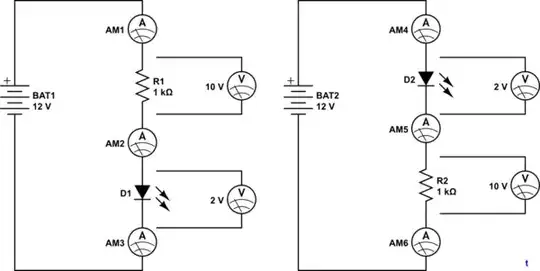
Figure 1. Simple circuit with multiple ammeters and voltmeters. Figure 2. The same circuit with the resistor and LED positions swapped.

In Figure 1 we have a simple 12 V battery powering an LED. The LED needs about 10 mA to light brightly and at that current will have nearly 2 V across it. That means we need a resistor to drop the other 10 V. From Ohm's Law we can calculate that \$ R = \frac {V}{I} = \frac {10}{0.01} = 1~k\Omega \$ so that's what we've got. We'll put three ammeters into the circuit to monitor current at every junction.

Conventional current flow is from '+' to '-'. This was decided before the electron was discovered by J. J. Thompson in 1897 and we still use it.

  • 10 mA will be leave the battery and go through AM1 to R1. AM1 will read 10 mA.
  • The 10 mA will continue through AM2 to D1. AM2 will read 10 mA.
  • The 10 mA will flow through D1 and through AM3. AM3 will read 10 mA.
  • The 10 mA will return to the battery.

If we use another dodgy water / hydraulic analogy, we can replace the battery with a hydraulic pump, pumping water clockwise around the circuit through a hydraulic motor. Clearly whatever water leaves the pump must return to it. There is no current lost.

There is, however, pressure loss. The pressure on the top of the circuit will be the pump pressure, the pressure at the bottom will be zero. The pressure at the junction between R1 and D1 will be somewhere in between.

In the same way the voltage at the top will be 12 V, the voltage at the bottom will be 0 V and the voltage at R1 / D1 will be somewhere in between.

It doesn't matter where in the circuit you put the control valve / resistor. The resultant current will be the same.


What's important is voltage drop across the component and not the voltage of any one terminal with respect to either of the battery terminals. As far as the LED is concerned having its terminals at 0 and 2 V is the same as having them at 10 and 12 V or 3.2 and 5.2 V, etc.

Transistor
  • 168,990
  • 12
  • 186
  • 385
  • Per my comments with simon and now you. what you said here " If we use another dodgy water analogy, we can replace the battery with a water pump, pumping water clockwise around the circuit. Clearly whatever water leaves the pump must return to it. " But the water (electrons) don't flow clockwise, they flow counter clockwise. everything I read says that! that electrons come out of the negative to the positive. and if that's true so is the fact that the electrical energy to the resistor is coming FIRST from the counterclockwise direction. So that's the side you would want to put your resistor. – Max R. Apr 24 '16 at 02:06
  • Not so. On a central heating radiator circuit you could put the valve on either side of the radiator. Yes, the pressure _with respect to the pump inlet_ would change but the pressure drop across each component would remain the same. See my updated answer. – Transistor Apr 24 '16 at 07:40
  • " Yes, the pressure with respect to the pump inlet would change but the pressure drop across each component would remain the same. " Agreed, but i'm not asking about the pressure of the water(voltage) I am asking about the START point of the water itself(electrons). And if the water itself(electrons) come out of the NEG terminal then.." It doesn't matter where in the circuit you put the control valve / resistor. The resultant current will be the same. " this can't be true because the water(electrons) being the source of energy when pressured(volts) needs to be resisted before the load, I think – Max R. Apr 24 '16 at 19:54
  • "_... the water(electrons) being the source of energy when pressured(volts) needs to be resisted before the load._" Nope. It doesn't matter. You still have the idea in your head that electrons are stronger near the battery. They're not. Every moving charge has the same force pushing it along. If you push a charge in at one end it comes out at the far end with the same 'force'. Same with the water. The flow or current is the same all the way around the loop. – Transistor Apr 24 '16 at 20:02
  • I just don't understand how something can start from one point go to another do a whole bunch of work and then leave exactly same like nothing happened. Like going to taco shop ordering food that's $12, getting your food, NOT paying the $12, telling the cashier "thanks" and leaving with $12 still in hand. – Max R. Apr 24 '16 at 20:19