2

As a newcomer to PIC programming, I am looking for some thoughts on how to implement SPI between a master and slave MCU the most efficient way.

The purpose of this system is to provide an extremely flexible way to 'map' up to 32 individual output pins of the slave MCU to any one of the 32 input pins of the master MCU, using a software-configurable 'matrix'.

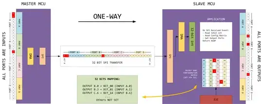
To make things a little more clear, I added a drawing below:

SPI FLOW

Some another MCU (not in the drawing) manages the port mapping setup and transfers this information to the slave MCU as a 'port matrix' via I2C.

In the drawing example, slave output port B, bit 0 (B.0) should be mapped to master input pin A, bit 0 (A.0) Furthermore, output B.3 should map to input A.1, and output C.6 should map to input B.6

So when master pin A.1 goes high, slave pin B.3 should go high too. From an application point of view, that should be staight-forward.

But what would be the most efficient way to read 32 bits from 4 ports on the master, and have them represented on the slave as a 32bit integer for the application to provide the mapping to its output ports?

SPI clock should at least be 2MHZ to be functionally acceptable. Is DMA a solution here? Can such transport solution be interrupt/event based in order to keep the CPU from polling stuff? Target MCU's are PIC32MX795.

I could definitely use some hints to get this communication going.

Thanks in advance!
Voltage Spike
  • 75,799
  • 36
  • 80
  • 208
  • What have you done so far, and why is it not good enough? I'd need more information. How are you defining "most efficient way"? E.g. least use of SPI bandwidth, fewest CPU cycles on slave, fewest CPU cycles on master, something else? How do the input pins change, one at a time, or random mixes of pins? What is the minimum input-pin change-duration which must be recognised and propagated? What is acceptable latency? Lowest latency between single pin input change, and output following it, or consistent latency no matter how many pins change? What's maximum latency for one and multipin changes? – gbulmer Apr 15 '16 at 16:15
  • This MCU based project is in conception phase. Current implementation is in hardware, but not flexible enough. Its purpose is to reuse CNC machine pulses. They appear random mixed on all pins. The current max pulse frequency is 400khz. Pulse durations around 1us. Master's only job is to sample input pins + transport. Slave function is limited to setting output ports according to the config matrix. Latencies up to 10 us are acceptable, if consistent. With most efficient, I meant the fastest setup, be it DMA or code, still learning about it. – Peterstevens Apr 15 '16 at 17:26
  • In the PIC32MX795, all the port *registers* are 32-bit, although only at most 16 bits are implemented. You show only 8 bits for each port. Okay, you just skip bits 8-15. But some of the port pins aren't implemented. I'll ignore port A, since the missing pins are in the high byte. But pins RC0, RC5, RC6, and RC7 are unavailable. See page 28 of the datasheet. Just so you know. – tcrosley Apr 15 '16 at 23:06
  • Using your latency requirement, 32 bits transferred from master to slave in 10usec needs a SPI clock no less than 3.2MHz and that ignores the time required for any processing. Using your 1usec pulse duration spec leads to a 32MHz SPI clock... – brhans Apr 16 '16 at 02:58
  • In fact, the 32 signals are part of a larger set. The 10us latency comes from our signals to stay in sync with other signals not in scope of the solution. If I change the routing, and make sure all critical signals pass through the solution, latency becomes much less stringent, as 1 ms would be ok. – Peterstevens Apr 16 '16 at 08:59
  • tcrosley, I know, the ports in the drawing are no real ports, they just serve the purpose of clarifying... thanks! – Peterstevens Apr 16 '16 at 09:00

3 Answers3

2

For the data transmission: easiest way to do this is with shift-registers. You will not need to worry about slow microcontrollers, neither about programming hardware in CPLDs.

Take for example 74HC164 and 74HC166

You can cascade four 74HC166 to create 32-bit parallel-in/serial-out shift register and then deserialize using four 74HC164 (32-bit serial-in/parallel-out register). These chips can do 100Mhz easily, cost next to nothing and require minimal circuitry around.

Problem is that "pin assignment matrix" you wanted to use. Building this with gates would be painful.

student
  • 541
  • 3
  • 12
0

If you are up for bit-banging the communication protocol yourself, the fastest way might be to use all 4 lines for sending the pin states (8 pins worth of data per line).

The idea here is to use basically a single-wire serial protocol. Since you will not have a clock line, you will need to use some sort of a start bit to identify beginning of transmission.

Let's say the data lines are held high when idle, and 0 is the start bit. If you want to transfer 0x12345678 worth of pin data (32 bits), you'd transfer 0x12 on the first line, 0x34 on the second line and so on.

The bit pattern on the first line will look like:

0 0 0 0 1 0 0 1 0

^ is the start bit

On the second line you would get:

0 0 0 1 1 0 1 0 0

^ is the start bit

You can see where I'm going with this. You might wish to add a checksum bit at the end to verify that you had no read errors. To implement this, you will need to wait for the line go low (you can use an interrupt for this), and from that point essentially implementing any other serial algorithm - sample the line several times per bit period (max duration of a single bit) and make sure the value is stable before you record it.

Then all you have to do is compact the data collected from all 4 lines using some bitshifts and write them straight to output.

Catsunami
  • 373
  • 1
  • 8
  • This wouldn't work - asynchronous comm. with word-based synchronization for 2Mhz rate would be difficult even if implemented in hardware. This is why RS-232 is so slow. – student Apr 15 '16 at 17:33
  • Well he said it would need 2MHz if he used SPI to transfer all 32 bits. This way you only need to transfer 8 bits at a time, so you can potentially take longer per bit. This is only bit-based synchronization. – Catsunami Apr 15 '16 at 17:37
  • It is not: bit synchronization requires PLL to lock on phase/freq of the transmitter. Word-based synchronization, however, synchronizes on phase in the edge generated with start bit. Then it samples few bits (8-10) in predefined intervals later hoping that the transmitter clock is close to its own clock. 2Mhz means period of 500ns for a bit, that is way to fast for the PIC. – student Apr 15 '16 at 17:44
  • This PIC? Its max frequency is 80MHz, the pins can even toggle at that frequency. This should be doable. Again, we don't need 2MHz if you only need to get 8 bits across. – Catsunami Apr 15 '16 at 18:12
  • You need to do phase synchronization on all of those parallel lines meaning you need to sample each bit at in about 10 places. So instead of having lets say 500kHz sampling rate you need 5Mhz. That means you have window of about 16 instructions to handle all 4 parallel comm. lines. Do you start to see why this is no good? Now, you can make your life so much easier if you just add 5th line for synchronization, because this will drop the need for phase synchronization and start bits, etc. – student Apr 16 '16 at 04:28
0

Your requirements are quite stringent (2Mhz, 10us delay) for it to be done in a PIC with few dozen MIPS. That being said, it might be possible. But its still not the best tool for the job.

Do you know FPGAs? They are too big and expensive for this, but some cheap little CPLD can do it too. Instead of writing software you would implement SPI bit banging in VHDL or Verilog on the master side and then slave could be your CNC controller, PIC, or another CPLD..

student
  • 541
  • 3
  • 12
  • I haven't learned about them CPLDs. Indeed an interresting alternative to look at. thanks! – Peterstevens Apr 15 '16 at 17:59
  • I thought of even simpler way of doing this and posted it for you as another answer – student Apr 16 '16 at 04:40
  • Suppose we change the design and go for CPLDs, that would solve the sampling issue on the master, would allow for any serial protocol to be implemented, and solves the issue of switching outputs as a matrix. the one thing that remains unclear to me is how to build some level of configuration freedom in a CPLD or some EEPROM or surrounding flash. We should be able to 'connect' outputs to inputs on the fly, not at compile time? – Peterstevens Apr 16 '16 at 09:20
  • Easy way to configure it online is to build another communication interface (can be SPI, UART, 1-wire, or even simple shift-register..) through which you write your configuration to internal registers. Their states will determine how the signals get routed. Just make sure that the configuration is done always in a state when the device does not read the parallel inputs - otherwise you might see spurious pulses (so-called hazards) in the serialized output. – student Apr 16 '16 at 15:31
  • Altera or Xilinx? What would the advice be for a newcomer? Not just the silicon, but also dev environment? – Peterstevens Apr 16 '16 at 16:37
  • I am not the right person to answer that - try to search it up here on EE or post a new question. – student Apr 17 '16 at 23:22
  • Ok Altera Max II dev boards have arrived. I've been looking at crosspoint switches for inspiration, reference designs are readily available. But this is not an exact match. From an architecture point of view, what would be the best way to implement such configuration register? – Peterstevens May 01 '16 at 19:09