I'm very new to electronics, but I'm trying to reverse the signal coming from a throttle position sensor as well as change the voltage range slightly. The throttle position sensor output signal range is 0.325v-4.75v. How can it be converted to a 4.5v-0.38v signal? I found a similar question on here, but I don't know what would need changed to fit my situation (Reversing a .5-4.5V analog sensor output to 5V-0V) or (How to invert a digital signal). I was told maybe a NPN transistor could be used??? But what size and what size resistors in the circuit to get the range to change? Thanks for any help!
Asked
Active
Viewed 1,806 times
4
-
Link to the other question, please. Put it **in your question** rather than in the comments so that others have all the info they need in the question. Welcome to EE.SE. – Transistor Mar 29 '16 at 23:36
-
@transistor I edited my question with the link to the similar question. Thank you – Nick M Mar 29 '16 at 23:43
-
1Got it. Your signal is not classed as digital but rather as an analog signal as the voltage is "analogous" to the position of the throttle. A simple NPN transistor circuit won't work in this case. Tell your source that "a rail-to-rail op-amp configured in inverting mode about a 2.5 V offset should do the trick." If you read my answer below a few times you might actually understand what you're telling him. ;^) – Transistor Mar 30 '16 at 00:08
2 Answers
2
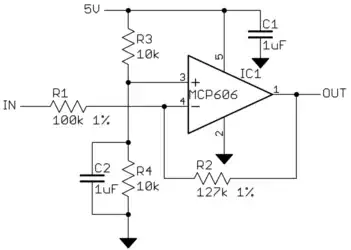
Use the same circuit as in the answer you linked to. In your case the maths is easier because it's an almost straight inversion.
For an inversion about a 2.5 V offset just change R2 to 100k. How it works:
- The op-amp (operational amplifier) is wired as an "inverting amplifier" with its gain calculated by \$ -\frac {R2}{R1} \$ and with equal values for R1 and R2 the gain is -1.
- The signal is inverted around the voltage set on the op-amp '+' input. R3 and R4 are equal so pin 3 is held at half-supply = 2.5 V. C2 holds that voltage steady in the event of any noise on the 5 V supply. C1 performs a similar function for the whole op-amp.
If you find that the controller isn't quite giving zero speed or full speed then increase the gain a little by increasing the value of R2 by adding series resistance to bring it up to 105 to 120 kΩ. The worst that will happen is that you will have a little "dead-zone" at one or both ends of the throttle. This will result in having to turn a few more degrees before the motor starts or / and reaching full power before the throttle is fully rotated. This will be better than not being able to fully reach zero or full power.
The MCP606 is chosen because it is a rail-to-rail op-amp. This means that it can control its output all the way from the negative rail (0 V) to the positive rail (5 V in your case) unlike some other op-amps which can only get within a volt or two of each rail.
More maths:
The full equation for the configuration is given by
$$ V_{OUT} = -(V_{IN} - V_3)G + V_3 = -(V_{IN} -V3) \frac {R_2}{R_1} + V_3 $$
where \$ G \$ is the gain and \$V_3\$ is the voltage on pin 3.
Let's sort out the gain, G, first.
The throttle position sensor output signal range is 0.325v-4.75v. How can it be converted to a 4.5v-0.38v signal?
From the data you provided the input span is 4.75 - 0.325 = 4.425 V and the output span is 4.5 - 0.38 = 4.12 V. So the gain we require is \$ \frac {SPAN_{OUT}}{SPAN_{IN}} = \frac {4.12}{4.425} = 0.931 \$ as you calculated in the comments. We can pop this value back into our equation:
$$ V_{OUT} = -0.93(V_{IN} - V_3)G + V_3 = -0.93 V_{IN} + 1.93 V_3$$
Solving this for \$ V_3 \$ gives
$$ V_3 = \frac {V_{OUT} + 0.93 V_{IN}}{1.93} $$
Putting in the values for one end of the throttle we get
$$ V_3 = \frac {4.5 + 0.93 \cdot 0.325}{1.93} = 2.49 V $$
Double-checking with the readings for the other end of the pot:
$$ V_3 = \frac {0.38 + 0.93 \cdot 4.75}{1.93} = 2.49 V $$
Bingo! 2.49 is 0.4% off 2.5 V so we'll go with 2.5 V which is conveniently half the 5 V supply. Set R3 and R4 to 10 kΩ.
Transistor
- 168,990
- 12
- 186
- 385
-
-
Thanks for the quick "accept" of my answer. You are generally advised to wait 24 h or so to see if a better answer comes along or if someone smarter spots a big flaw in my solution. If it does happen you can select the other answer. Welcome to EE.SE. Good first question. +1. – Transistor Mar 30 '16 at 00:18
-
I've been trying to study this and figure out how it all works and do the calculations, but I think I'm doing something wrong. Using the math in the answer in that other link I believe that the exact gain should be -0.931. I found this by finding the difference of the input range (4.75-0.325=4.425) and the difference of the output range (4.50-0.38=4.12). Then 4.12/4.425=0.931. If I take the formula V-out=Gain*(V+ - V-), then I get 5.16 V that needs to come from the voltage divider, which doesn't make sense – Nick M Mar 30 '16 at 19:01
-
Perfectly correct on your calculations for the gain of -0.931. So if we go for a gain of -1 that would be 7% or 3 or 4% dead zone at each end of the throttle which you would be very unlikely to notice. Your resistors, power supply voltage and throttle will all have a tolerance so my approach would be to try it out and adjust if required. I monitor the site regularly so ask another question if you get stuck. – Transistor Mar 30 '16 at 19:23
-
As a matter of interest, is the throttle from an electric bike? Have you got a part number? There's a small chance that you can reverse the output by reversing the polarity of the magnet but the mechanisms can be difficult to reassemble. – Transistor Mar 30 '16 at 19:26
-
No the throttle position sensor is on the throttle blade of an engine that I'm building. The throttle blade is electronically actuated from the pedal, but the sensor on the throttle blade tells the Engine control module the angle of the throttle for verification. The ECM is expecting the 0.38v-4.5v signal but my throttle blade sensor out of a newer vehicle gives the 4.75v-0.325v signal. If the signal is out if the range that the ECM is expecting, it will shut down and go into protect mode or "limp mode" – Nick M Mar 30 '16 at 19:34
-
is solving for V+ in this equation Vout=Gain*(V+ - V-) not the correct way to determine to voltage that needs to go to pin 3 in that diagram? 4.5= -0.93*(V+ - 0.325) would actally be -4.514 – Nick M Mar 30 '16 at 19:42
-
I think you've mixed up a sign somewhere (as I did in trying to work it out). See the update. – Transistor Mar 30 '16 at 20:33
-
OK thank you so much for clearing that up for me! I definitely must have mixed something up when I was calculating – Nick M Mar 30 '16 at 20:44
-
Hello @Transistor, sorry for adding more comments, but I don't have enough reputation yet to use chat. I tried building this circuit and for some reason it isn't working. The input voltage is reading the same as the output voltage. Is there something in particular that might cause it to not inverse the signal? http://www.mouser.com/Search/ProductDetail.aspx?R=MCP606-I%2fPvirtualkey57940000virtualkey579-MCP606-I%2fP here is the OP-amp I am using – Nick M Apr 27 '16 at 15:47
-
Here are some pictures of the circuit I made. I was using the Pot. to try to get the gain dialed in. I'm sure it's impossible to tell exactly what I did from these pictures... http://i105.photobucket.com/albums/m236/sjfggoiskf/20160426_060211_zpsblvy10gw.jpg[i105.photobucket.com] http://i105.photobucket.com/albums/m236/sjfggoiskf/20160426_060318_zpsbss0daff.jpg[i105.photobucket.com] http://i105.photobucket.com/albums/m236/sjfggoiskf/20160426_060424_zpsekq2nk3v.jpg[i105.photobucket.com] http://i105.photobucket.com/albums/m236/sjfggoiskf/20160426_060533_zpstw4xwqu8.jpg[i105.photobucket.com] – Nick M Apr 27 '16 at 15:52
-
Your soldering looks half decent but your layout is a shambles! You have a wire - probably your "output" connected to pin 5 which the datasheet says in NC (not connected). You have no connection to pin 6, the output. – Transistor Apr 27 '16 at 20:26
-
wow that's embarrasing! I looked it over like 3 times thinking I had it all hooked up correctly. How did I miss that! I will move the wire and test it again. Thanks! And Yeah the layout did turn out pretty bad. This was certainly a learning experience for me. This was my first project like this. Thanks again for the help! I will report back if it works or not. – Nick M Apr 27 '16 at 20:38
-
Best way to look good on strip like that is to run components perpendicular to the tracks under the board. Use spare tracks > 1 resistor length away from the pin you need to connect to. You can also stand resistors perpendicular to the board and make a hairpin bend in the top leg to get back down to the adjacent track. See [Stripboard](https://en.wikipedia.org/wiki/Stripboard) on Wikipedia for one or two nice examples. Take heart. At least you realised that the pinout is different to the schematic in my answer. – Transistor Apr 27 '16 at 20:57
0
By reversing the magnet position (the magnet is inside the throttle, the throttle needs to be dismantled, which isn't difficult). The poles will change (north with south) and you will have almost 5v at beginning and drop to 0.8v at max.
Voltage Spike
- 75,799
- 36
- 80
- 208
-
Welcome to EE.SE. That doesn't always work. How do I know? I tried it. Please capitalise and punctuate your sentences properly. It's site policy. See [Write to the best of your ability](https://electronics.stackexchange.com/help/how-to-answer) on the site's help pages. – Transistor Apr 02 '19 at 21:13