Think of a BJT as a valve. By default, the valve is off. No current can flow through our valve. In order to get our valve to turn, we need to make current flow through the base of the BJT. This lets current flow through the transistor, from the collector to emitter. The more current we apply to the base, the more open our valve becomes.
In your first diagram, current can reach the base the BJT, which turns it on. I have drawn the current flow with red arrows.
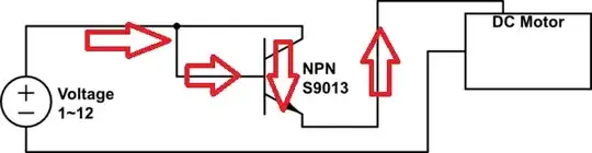
Current can flow through the base and the collector of the BJT, which turns it on.
Now, in your second picture, the current cannot reach the base of the BJT because the BJT is turned off.
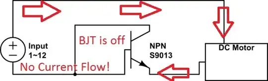
In addition, the BJT is in there backwards. The current needs to flow from the collector to the emitter. The way it is wired, the current tries to flow from the emitter to the collector. The current can't reach the base to turn the BJT on because the BJT is off. There's a chicken-and-egg problem with the second schematic.
You can put the BJT on either side of the DC motor, but it has to be wired correctly in order to work.
To fix the second image, run the line from the motor to the collector. Connect the collector and the base together, and connect the emitter to the negative on the power supply.


